Do you have a question about the Aruba 6000 series and is the answer not in the manual?
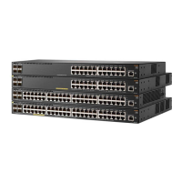
| Model | Aruba 6000 Series |
|---|---|
| Operating Temperature | 0°C to 45°C (32°F to 113°F) |
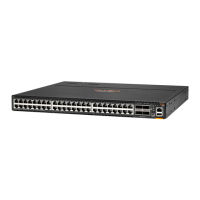
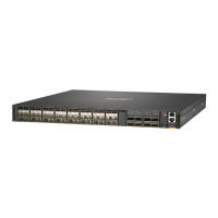
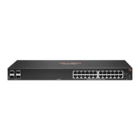
| Uplink Ports | 4 SFP+ ports |
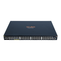
| PoE | Available on some models (PoE+) |
| Switching Capacity | 176 Gbps |
| Layer | Layer 2/3 |
| Management | CLI, SNMP |
| Input Voltage | 100-240VAC |
| Power Supply | Internal |
| Ports | 24 or 48 10/100/1000BASE-T ports |