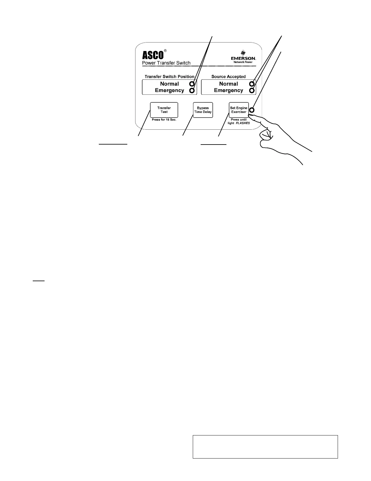
Hold 15 sec.to
start the engine
generator and to
transfer the load
to emergency.
Press to cancel the
active exercise period
(stops engine now or
after cooldown) See
page 5–1.
Hold 5 sec
.toset
20 min. engine exercise
period immediately (engine
starts) and weekly thereafter.
³ blinks slowly when
button is released (set)
and during 20 min.
exercise period.
³ blinks rapidly when
button is held 5 sec.
while being set
Lights show position of transfer switch.
Lights show the sources accepted.
Light for built–in
engine exercise timer:
Seepage5–1
for complete
instructions
Figure 2–1. Membrane controls and indicator lights.
³ stays on after engine
stops (exerciser is
enabled for weekly
operation)
SECTION 2 SEQUENCE OF OPERATION
2 --- 1
Transfer To Emergency
Thesequenceforloadtransferto
emerg en cy source beg ins automati-
cally when normal source voltage
falls below the preset dropout point
or when Transfer Test button i s
pressed. An under voltage condition
on any phase of the normal source is
detected by the sens or.
Whe n th e no rma l
sour c e voltag e fails or
the Transf e r Test button
is pressed, the SE relay
de-energ iz es and relay
NR begins its timing
cycle (1 or 3 seconds,
momen t ar y no rmal
source outage delay).
The NR relay is provid ed with a time delay on dropout to
overr ide momen tary outages and prevent nuisance starting
of the engine-driven generator. If the normal source voltage
retur ns above the sensor dr opo ut setting before the tim e
delay expire s , the NR rela y timing cyc le is res et to ze r o and
relay SE energizes.
If the normal source voltage does not return above the
sensor dropout setting befor e the time delay expires, the
NR relay de-energ iz es and signals the engine-driven
gen erator to start. At the sam e time, a vol tag e and
frequenc y sensor begins monitoring the emerg enc y source.
The sensor will accept the emergency source only when
both
voltage and frequency reach preset pickup points.
Usually about ten seconds elapse from dropout of the NR
relay to acceptance by the sensor. This time span occurs
bec ause the engine-d riven generator mus t crank, start, and
run up to nom inal pickup poin ts. For this reaso n, if the
Tra nsfer Test button is pressed it must be held for 15 seconds.
If the emergency sourc e is availab l e immediately, the sensor
may accept it as soon as NR relay drops out.
When the emergency source is accepted by the sensor,
relay ER begins its timing cycle (transfer to emergency
delay). ER relay is provided with an adjustable (0 to 5
minutes) time delay on pickup to delay transfer of the
load to the emergency source. F or immediate transfer
press Bypass Time Delay button.
ER relay energizes, the TS coil is energized, the transfer
switch operates, and all switch contacts (mains, controls,
auxiliaries) reverse position. The transfer switch is now
supplying the load from the emergency source.
The tra nsfer switch will remai n i n the Emergency
positi on unt il the normal source i s restored. If t he
Transfer Test button is used, the transfer switch will
remain on emergency until the retransfer to normal delay
times out.
Retransfer to Normal
The sequence for load retransfer to the normal source
automatically begi ns when the voltage sensor detects
restoration of the normal source. The voltage level must
rise above the preset pickup point on all phases before
the sensor will accept the normal source.
W
henthenormalsourceisacceptedbythesensor,relay
SE begins its timing cycle (adjustable 1 sec. to 30 min.,
retransfer to normal delay). For immediate retransfer
press Bypass Time Delay button. SE relay is provided with
a time delay on pickup to prevent immediate load
retransfer to the normal source. The delay insures that
the normal source has stabilized before reconnection of
vital loads. If the normal source voltage falls below the
present dropout point before the time delay expires, the
timing cycle is reset to zero. If the emergency source fails
for more than 4 seconds during t he timing cycle, ER relay
drops out and the load is immediately retransferred to
the normal source, if that source is acceptable.
SE relay energizes a nd ER relay is dropped out. The TS
coil is energized, the transfer switch operates, and all
switch contacts (mains, controls, auxiliaries) reverse
position. The transfer switch is now supplying the load
from the normal source again.
Upon retransfer to the normalsource, NR relay begins its
timing cycle (unloaded running delay [engine cooldown] ).
NRrelay is provided witha 5 minute timedelay onpickup
to keep the engine runni ng for a cool-down period.
NR relay energizes after the time delay and signals the
engine-driven generator to shut down. All circuits are
reset for any future normal source failure.
Activation of standard control features shown in Section 5
will alter the sequence of operation and in trod uce
additional time delays during transfer operations.

 Loading...