INSTALLATION (continued)
1 --- 5
pressthisbutton
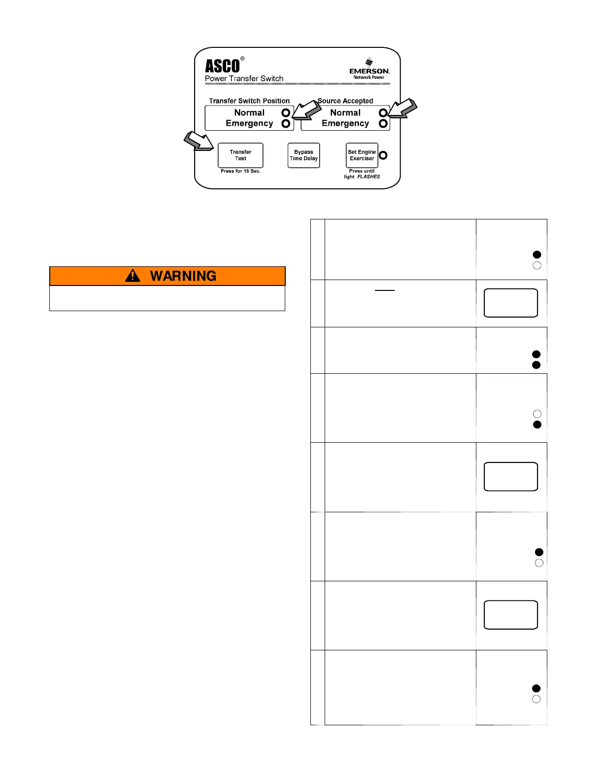
observe these lights
Figure 1–6. Standard controls and indicators.
3 – Electrical Operation
This procedure will check the electrical opertion of the
Automatic Transfer Switch.
Close the enclosure door first !
Transfer Test
Both normal and emergency sources must be available and
the emergency source generator (if used) must be capable
of being started in this procedure.
Perform steps 1 through 8 at the right. Observe the status
lights. See Figure 1–6.
● Black circle means light is on.
❍ White circle means light is off.
NOTE: IfMotorLoadTransferfeatureis
activated, then transfer may not occur
immediately after the respective time
delays. Transf er will o nly occur when the
phase relationship between sources is
correct.
This com pletes the Functional Test of the A SCO Series 300
Automatic Transfer Switc h . Leave the engine–generator
starting control in the automatic position.
1
The normal source must be
availableandthegenerator
must be ready to start.
Check t hat the Normal Source
Accepted light is on.
Source Accepted
Normal
Emergency
2
Press and hold the Transfer Test
button until the engine starts
and runs. This should happen
within 15 sec.
Transfer
Tes t
3
The Emergency Source
Accepted light should come on.
Source Accepted
Normal
Emergency
4
The transfer switch should
transfer to the Emergency
position. The Emergency
Transfer Switch Position light
should come on and the Normal
light should go off.
Transfer Switch
Position
Normal
Emergency
5
If the transfer to emergency
delay is used the transfer
should occurs after a time delay
(up to 5 minutes).
Forimmediatetransferpress
the Bypass Time Delay button.
Bypass
Time Delay
6
The transfer switch should
transfer back to the Normal
position. The Normal Transfer
Switch Position light should
come on a nd the Emergency
light should go off.
Transfer Switch
Position
Normal
Emergency
7
If the retransfer to normal delay
is used the retransfer should
occur after a time delay
(up to 30 minutes).
Forimmediateretransferpress
the Bypass Time Delay button.
Bypass
Time Delay
8
The unloaded running delay
keeps the generator running for
5 minutes (cool–down period).
Then the generator should stop
and the Emergency Source
Accepted light should go off.
Source Accepted
Normal
Emergency

 Loading...