INSTALLATION (continued)
1 --- 4
observe these lights
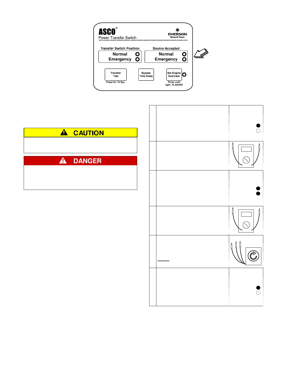
Figure 1–5. Standard controls and indicators.
2–VoltageChecks
First check nameplate on transfer switch; rated voltage
mustbethesameasnormalandemergencylinevoltages.
Verify that the feeders have been
connected to the proper lugs.
Use extreme caution when using a meter
to measure voltages in the following
steps. Do not touch power terminals;
sh oc k , burns , or death could result !
Perform steps 1 through 6 at the right. Observe the status
lights. See Figure 1–5.
● Black circle means light is on.
❍ White circle means light is off.
* If necessary, adjust voltage regulator on the generator
according to the manufacturer’s recommendations. The
Automatic Transfer Switch will respond only to the rated
voltage specified on the Transfer Switch nameplate.
Also see page 4–1 for the HI–LOW voltage adjust setting in
the controller. The LOW setting shifts all voltage settings
down 4. 2%; for example, 240 V to 230 V.
1
Close the normal source circuit
breaker. The Normal T ransfer
Switch Position and the Normal
Source Accepted lights should
come on.
Source Accepted
Normal
Emergency
2
Use an accurate voltmeter to
check phase to phase and
phase to neutral voltages pres-
entatthetransferswitchnormal
source terminals.
3
Close the emergency source
circuit breaker. (Start generator,
if necessary.) The Emergency
Source Accepted light should
come on.
Source Accepted
Normal
Emergency
4
Use an accurate voltmeter to
check phase to phase and
phase to neutral voltages pres-
ent a t the transfer switch emer-
gency source terminals.*
5
Useaphaserotationmeterto
check phase rotation of emer-
gency source; it must be the
same
as the normal source.
A
B
C
6
Shut down the engine–genera-
tor, if applicable. The Emergen-
cy Source Accepted light should
go off. Then put the starting
control selector sw itch (on the
generator set) in the automatic
position. Close enclosure door.
Source Accepted
Normal
Emergency
Now continue to 3 – Electrical Operation on next page.

 Loading...