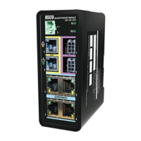
5170 Quad-Ethernet Module Modbus & ASCOBusII TCP Interfaces 4-1
TCP/IP Modbus (for Monitoring Systems)
The 5170 QEM can act as a Modbus server to provide data to a Modbus client on demand over TCP/IP Intranet.
The 5170 QEM looks transparent to the Modbus client. The Modbus register in the downstream device looks like it
is inside the 5170 QEM. Because the 5170 QEM acts as a data concentrator, the data from downstream devices is
constantly updated and available in the 5170 QEM. This design results in a very fast turn-around time.
To be able to control a Transfer Switch (TS), you need to set up a password. Configuration → Ethernet Module
→ Edit → Login Password. From Advanced, click Modbus Control Password.
Accessing Modbus Data
Accessing parameters by Modbus requires three components over TCP/IP: the IP Address, the TCP Port device
address, and the Modbus Register number. Modbus is always enabled in the 5170 QEM.
IP Address
The IP Address required to allow a master the ability to communicate to the 5170 QEM is defined in the
configuration pages of the 5170 QEM web server,
ETHERNET TCP/IP v4 BLOCK.
The Modbus/TCP Client is on the same network as the Modbus/TCP server (the 5170 QEM).
Device Address
The 5170 QEM maps the Modbus data using an alias table to define must be device addressing. This is the device
address needed when configuring the Modbus client. This address can be accessed from the Configuration →
Ethernet Module page of the 5170 QEM webpage, TCP/IP MODBUS PARAMETER BLOCK.
The Modbus address for Group 5 controller and 5200 Series Meter as configured in the 5170 QEM as 1 and 2
respectively.
Note The Meter Connected setting is set to zero. This means that MODBUS communication over TCP for the
Power Meter is disabled even though there was a assigned address of 2. To enable this, set meter connected
value to 1.
Modbus Register
The Modbus register map is the same as that of the downstream device. As an example, the line-to-line voltage
(A-B) of the 4000 &7000 Transfer Switch’s Group 5 Controller is at register address 40017. Reading this same
register from the 5170 QEM will provide the data from the Group 5 Controller to the Modbus client.
The TCP port setting is done on the Configuration/Ethernet Module page, ETHERNET TCP/IPv4 BLOCK.
The port is defaulted to 10001. For an example interface using the Modbus Test Suite refer to document 381339-319.
NOTE The Modbus and ASCOBus II protocols use the same port address
ASCOBusII / TCP Interface
ASCOBusII is a proprietary protocol designed by ASCO Power Technologies for use with ASCO 5700 & 5900 Series
CPMS systems. Accessing ASCOBusII data requires an ASCO Power Technologies technician. ASCOBus II is
always enabled in the 5170 QEM and cannot be disabled.
The downstream Group 5 Controller and Series 5200 Meter (when present) must both be
configured to be ASCOBusII, 19200 baud and both assigned as address 1 regardless of the
(upstream) Ethernet protocols being used. These settings CAN NOT be changed from the 5170
QEM webpages
.

 Loading...