Page 1 of 8 (Section 1 of 2)Printed in U.S.A.
MMIII All Rights Reserved.
50 Hanover Road, Florham Park, New Jersey 07932 www.ascovalve.com
Installation & Maintenance Instructions
SERIES
Form No.V6928R3 - Sec. 1
3-WAY INTERNAL OR EXTERNAL PILOTED SOLENOID VALVES
8316
NORMALLY CLOSED OPERATION Ċ AIR OR INERT GAS SERVICE
1/4I, 3/8I OR 1/2I NPT Ċ 5/16I OR 5/8I ORIFICE
(Section 1 of 2)
NOTICE: See separate solenoid installation and maintenance
instructions for information on: Wiring, Solenoid
Temperature, Causes of Improper Operation, and Solenoid
Replacement.
For exploded views, see Form No. V6928R3 - Section 2 of 2.
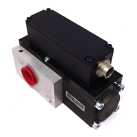
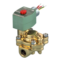
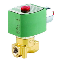
DESCRIPTION
Series 8316 valves are 3-way solenoid valves designed for air
or inert gas service. Depending upon requirements, this valve
may be used in either the Internal Piloting Mode or External
Piloting Mode of operation. This unique valve design allows
the user to relocate (turn over) the Support with Flow Gaskets
to change the mode of valve operation. For additional
information on valve operation, see sections on OPERATION
and CHANGING MODE OF OPERATION.
Series 8316 valves are available in three solenoid versions;
standard, low power and intrinsically safe. Valves are rugged
forged brass with internal parts of stainless steel and low
temperature Buna N elastomers.
NOTICE
This valve is supplied from the factory in the Internal
Piloting Mode of operation. Refer to OPERATION -
INTERNAL PILOTING MODE following.
To change valve mode of operation to External
Piloting Mode, see section on CHANGING MODE
OF OPERATION on page 2 of 6.
OPERATION - INTERNAL PILOTING MODE
IMPORTANT: Internal piloted valves require a minimum
operating pressure differential of 15 psi.
Normally Closed
Solenoid De-energized: Flow is from cylinder CYL" to main
exhaust EXH". Internal pressure is vented briefly through
pilot exhaust. Pressure PRESS" is closed.
Solenoid Energized: Flow is from pressure PRESS" to
cylinder CYL". Main exhaust EXH" and pilot exhaust are
closed.
Flow Diagrams
Solenoid De-Energized Solenoid Energized
EXH EXH
PILOT EXH PILOT EXH
PRESSPRESS
CYL CYL
(main)
(main)
OPERATION - EXTERNAL PILOTING MODE
The external piloting mode of operation allows a zero
minimum main line pressure with the application of proper
auxiliary air pressure. Refer to operating instructions (to
follow) and the graph Auxiliary Pilot Pressure vs Main Line
Pressure. Use this graph to determine the minimum auxiliary
air pressure required for a given main line pressure.
Normally Closed
Solenoid De-energized with Auxiliary Pressure Applied: Flow
is from cylinder CYL" to main exhaust EXH". Internal
pressure is vented briefly through pilot exhaust. Pressure
PRESS" is closed.
Solenoid Energized with Auxiliary Pressure Applied: Flow is
from pressure PRESS" to cylinder CYL". Main exhaust
EXH" and pilot exhaust are closed.
Flow Diagrams
Solenoid De-Energized
with Auxiliary Pressure
Applied
Solenoid Energized
with Auxiliary Pressure
Applied
EXH
PILOT EXH
PRESS
CYL
EXH
PILOT EXH
PRESS
CYL
AUX AUX
(main) (main)
Note: If main line pressure is lost, with solenoid de-energized
or energized external piloted valves will not change position as
long as auxiliary pilot pressure is present. If auxiliary pilot
pressure is lost while main line pressure is present, valve will
change position if solenoid is energized, but will not change
position if solenoid is de-energized.
120
105
90
75
60
45
30
15
0
0 15 30 45 60 75 90 105 120 135 150
Auxiliary Pilot Pressure vs Main Line Pressure
Main Line Pressure PSI
Auxiliary Pilot Pressure PSI