Page 6 of 8 (Section 2 of 2) Form No.V6928R3 - Sec. 2
50 Hanover Road, Florham Park, New Jersey 07932 www.ascovalve.com
Torque Chart
Part Name
(see note)
Wrench Size
or Tool
Torque Value
Inch-Pounds
Torque Value
Newton-Meters
Cartridge assembly 1 1/8I
Solenoid base sub-assembly 1I
175 ± 25 19,8 ± 2,8
Bonnet screws 7/16I 95 ± 10 10,7 ± 1,1
Cover screws screw driver 13 ± 1 1,5 ± 0,1
Pipe adapter 11/16I 90 maximum 10,2 maximum
Note: Thread all parts by hand as far as possible. Then torque evenly in a crisscross manner where applicable.
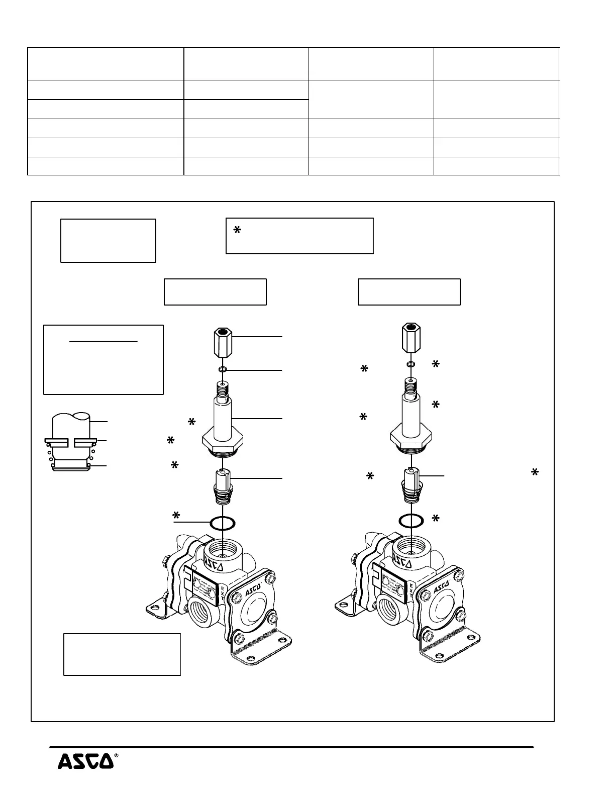
Figure 6. Partial view of solenoid parts for standard valve constructions. See Figures 7 or 8
for disassembly and reassembly of main valve body.
core assembly
core spring
core guide
IMPORTANT
Partial cutaway view
showing positioning
of core guide on
core assembly.
Indicates parts supplied
in ASCO Rebuild Kit
DC ConstructionAC Construction
core assembly
(with core spring)
pipe adapter
plugnut gasket
solenoid base
sub-assembly
core assembly
(with core guide
and core spring)
solenoid base gasket
(1/4I NPT)
5/16I orifice valve
construction shown
See Torque and
Lubrication Chart
Important

 Loading...