Page 5 of 8 (Section 2 of 2)
Printed in U.S.A.
MMIII All Rights Reserved.
50 Hanover Road, Florham Park, New Jersey 07932 www.ascovalve.com
Installation & Maintenance Instructions
SERIES
Form No.V6928R3 - Sec. 2
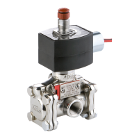
3-WAY INTERNAL OR EXTERNAL PILOTED SOLENOID VALVES 8316
NORMALLY CLOSED OPERATION Ċ AIR OR INERT GAS SERVICE
(Section 2 of 2)
1/4I, 3/8I OR 1/2I NPT Ċ 5/16I OR 5/8I ORIFICE
NOTICE: See Form No. V6928R3 - Section 1 of 2.
continued from Form No. V6928R3 - Section 1 of 2
Valve Reassembly
1. Lubricate cartridge gasket, orifice gasket, plugnut gasket,
solenoid base gasket and large and small flow gaskets with
DOW CORNINGr 200 Fluid lubricant or an equivalent
high-grade silicone fluid lubricant.
2. Lubricate body gaskets (2), body passage gasket and
retaining ring with DOW CORNINGr 111 Compound
lubricant or an equivalent high-grade silicone grease.
3. Install valve stem in disc assembly. Then install disc
assembly (with valve stem), body gasket, disc spring, end
cap, and bonnet screws with lockwashers. Hand thread
screws a few turns into valve body. Then torque bonnet
screws in a crisscross manner to 95 ± 10 in-lbs
[10,7 ± 1,1 Nm].
4. Install diaphragm support (see note below), body gasket,
diaphragm assembly (engaged to valve stem), body
passage gasket, retaining ring, valve bonnet and bonnet
screws with lockwashers. Torque bonnet screws according
to instructions in step 3.
NOTE: Retaining ring and diaphragm support are only present
on 5/8I orifice valve constructions. However, they are not present
on all 5/8I orifice valve constructions.
5. Low Power & Intrinsically Safe - Position cartridge gasket
in valve body. Then install orifice gasket in recess in base
of cartridge assembly. Thread cartridge assembly with
orifice gasket into valve body. Then torque cartridge
assembly to 175 ± 25 in-lbs [19,8 ± 2,8 Nm].
Standard Valves - Replace solenoid base gasket, core
assembly and solenoid base sub-assembly. Torque
solenoid base sub-assembly to 175 ± 25 in-lbs
[19,8 ± 2,8 Nm]. Install plugnut gasket on solenoid base
sub-assembly.
6. Before installing flow gaskets, support, cover and cover
screws, refer to section on CHANGING MODE OF
OPERATION for the proper mode of operation and
positioning of parts.
7. Install large and small flow gaskets in the support. Large
gasket must be compressed to fit support configuration.
8. Orient the support (with flow gaskets) to the proper pilot
flow mode of operation and position against side wall of
valve body with flow orifices. Then install cover and two
cover screws. Torque screws evenly to 13 ± 1 in-lbs
[1,5 ± 0,1 Nm].
9. Install solenoid, see separate instructions. Then make
electrical connection to solenoid.
10. Install muffler or make up piping to pilot exhaust on top
of solenoid.
WARNING: To prevent the possibility of death,
personal injury or property damage, check valve
for proper operation before returning to service.
Also perform internal seat and external leakage
tests with a nonhazardous, noncombustible fluid.
11. Restore line pressure and electrical power supply to valve.
12. After maintenance is completed, operate the valve a few
times to be sure of proper operation.
ORDERING INFORMATION
FOR ASCO REBUILD KITS
Parts marked with an asterisk (*) in the exploded view are
supplied in Rebuild Kits. When Ordering Rebuild Kits for
ASCO valves, order the Rebuild Kit number stamped on the
valve nameplate. If the number of the kit is not visible, order
by indicating the number of kits required, and the Catalog
Number and Serial Number of the valve(s) for which they are
intended.
Lubrication Chart
Lubrication Parts to be lubricated
DOW CORNINGr 111 Compound lubricant or
an equivalent high-grade silicone grease.
body passage gasket retaining ring
body gaskets (2)
DOW CORNINGr 200 Fluid lubricant or
an equivalent high-grade silicone fluid.
orifice gasket plugnut gasket
cartridge gasket solenoid base gasket
large flow gasket
small flow gasket

 Loading...