Page 4 of 8 (Section 1 of 2) Form No.V6928R3 - Sec. 1
50 Hanover Road, Florham Park, New Jersey 07932 www.ascovalve.com
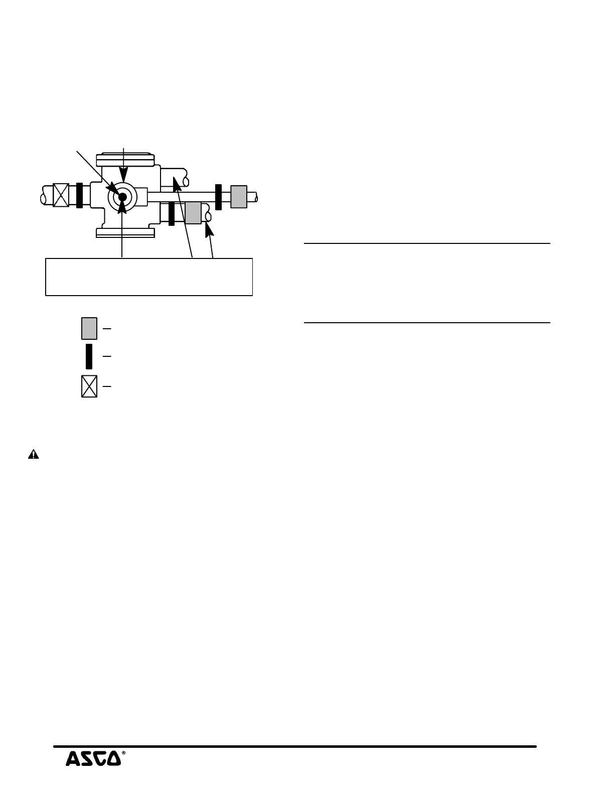
Flow Controls (Speed or Metering Devices)
Flow control valves may be added to control cylinder speed. If
used, these flow control valves must be located in cylinder
piping between the solenoid valve and the cylinder.
IMPORTANT: Do not install flow controls (speed or
metering devices) or any type of restrictive device in the
pressure (inlet), exhaust or pilot exhaust (outlet) ports of
the valve. Restricting any of these lines may cause valve
malfunction.
Cyl.
Press.
Aux.
Pilot Exh.
Indicates location
of pressure gauge
Indicates location
of filter
Indicates location
of metering device
Main
Exh.
muffler
or piping
Solenoid
Figure 5. Piping diagram
For Internal Piloting Mode only: Full size
piping without restrictions must be used
on pressure and exhaust lines.
MAINTENANCE
WARNING: To prevent the possibility of death,
personal injury or property damage, turn off
electrical power, depressurize valve, and vent
fluid to a safe area before servicing the valve.
NOTE: It is not necessary to remove the valve from the pipeline
for repairs. However, piping or tubing must be removed from
pilot exhaust on top of the solenoid if present. See Piping
section.
Cleaning
All solenoid valves should be cleaned periodically. The time
between cleanings will vary depending on the medium and
service conditions. In general, if the voltage to the coil is
correct, sluggish valve operation, excessive noise or leakage will
indicate that cleaning is required. In the extreme case, faulty
valve operation will occur and the valve may fail to shift. Clean
filter when cleaning the valve.
Preventive Maintenance
S Keep the medium flowing through the valve as free from dirt
and foreign material as possible.
S Periodic exercise of the valve should be considered if
ambient or fluid conditions are such that corrosion,
elastomer degradation, fluid contamination build up or
other conditions that could impede solenoid valve shifting
are possible. In many cases, solenoid valves are periodically
exercised during normal system use or as part of routine
maintenance or surveillance activities and no additional
exercise is necessary. The actual frequency of exercise
necessary will depend on specific operating conditions. A
successful operating history is the best indication of a proper
interval between exercise cycles.
S Depending on the medium and service conditions, periodic
inspection of internal valve parts for damage or excessive
wear is recommended. Thoroughly clean all parts. If parts
are worn or damaged, install a complete ASCO Rebuild Kit.
Causes of Improper Operation
S Incorrect Pressure: Check valve pressure. Pressure to valve
must be within range specified on nameplate.
S Excessive Leakage: Disassemble valve and clean all parts. If
parts are worn or damaged, install a complete ASCO
Rebuild Kit.
Valve Disassembly
NOTICE: Basic valve constructions are identified by orifice
size and pipe size (NPT). Check valve nameplate for orifice and
pipe size. See Figure 7 for 5/16I orifice, 1/4I or 3/8I NPT;
Figure 8 for 5/8I orifice, 3/8I or 1/2I NPT. For Standard valve
solenoid parts see Figure 6 in addition to Figures 7 or 8. Figures
7 and 8 show Low Power and Intrinsically Safe solenoid parts.
Determine valve construction and proceed as follows:
1. Disassemble valve in an orderly fashion using exploded
views for identification and placement of parts.
2. Low Power & Intrinsically Safe - Using a suitable wrench
hold cartridge assembly securely by wrenching flats. Then
unscrew muffler or piping from 1/8I NPT connection on
top of cartridge assembly.
Standard Valves - Hold pipe adapter securely and
unscrew muffler or piping from 1/4I NPT connection on
top of solenoid base sub-assembly.
3. Remove solenoid, see separate instructions.
4. Low Power & Intrinsically Safe - Unscrew cartridge
assembly from valve body. Then remove cartridge gasket
from valve body and orifice gasket from recess in base of
cartridge assembly.
Standard Valves - Unscrew solenoid base sub-assembly
from valve body. Then remove solenoid base gasket and
core assembly with core spring and core guide. Core guide
present on AC construction only. Remove plugnut gasket
from groove in solenoid base sub-assembly.
5. Remove cover screws (2), cover, and support containing
large and small flow gaskets from side of valve body.
6. At exhaust end, remove bonnet screws, lockwashers, valve
bonnet, body passage gasket, retaining ring, diaphragm
assembly, diaphragm support (see note below) and body
gasket from valve body.
NOTE: Retaining ring and diaphragm support are only present
on 5/8I orifice valve constructions. However, they are not present
on all 5/8I orifice valve constructions.
7. At opposite end remove bonnet screws, lockwashers, end
cap, disc spring, body gasket, disc assembly and valve stem.
8. All parts are now accessible for cleaning or replacement.
If parts are worn or damaged, install a complete ASCO
Rebuild Kit.
continued on Form No. V6928R3 - Section 2 of 2

 Loading...