Page 3 of 8 (Section 1 of 2)Form No.V6928R3 - Sec. 1
50 Hanover Road, Florham Park, New Jersey 07932 www.ascovalve.com
INSTALLATION
Check nameplate for correct catalog number, pressure,
voltage, frequency, and service. Never apply incompatible
fluids or exceed pressure rating of the valve. Installation and
valve maintenance to be performed by qualified personnel.
Future Service Considerations
Provision should be made for performing seat leakage, external
leakage, and operational tests on the valve with a
nonhazardous, noncombustible fluid after disassembly and
reassembly.
Temperature Limitations
Ambient and Fluid Temperature Ranges:
S Standard Valves:
AC Construction -4_F (- 20_C) to 125_F (54_C):
DC Construction - 4_F (- 20_C) to 104_F (40_C):
S Low Power &
Intrinsically Safe: -20_F (- 29_C) to 140_F (60_C):
: For optimum performance, not recommended below 32_F
(0_C) on Suffix V" elastomer constructions.
Positioning
Valve may be mounted in any position.
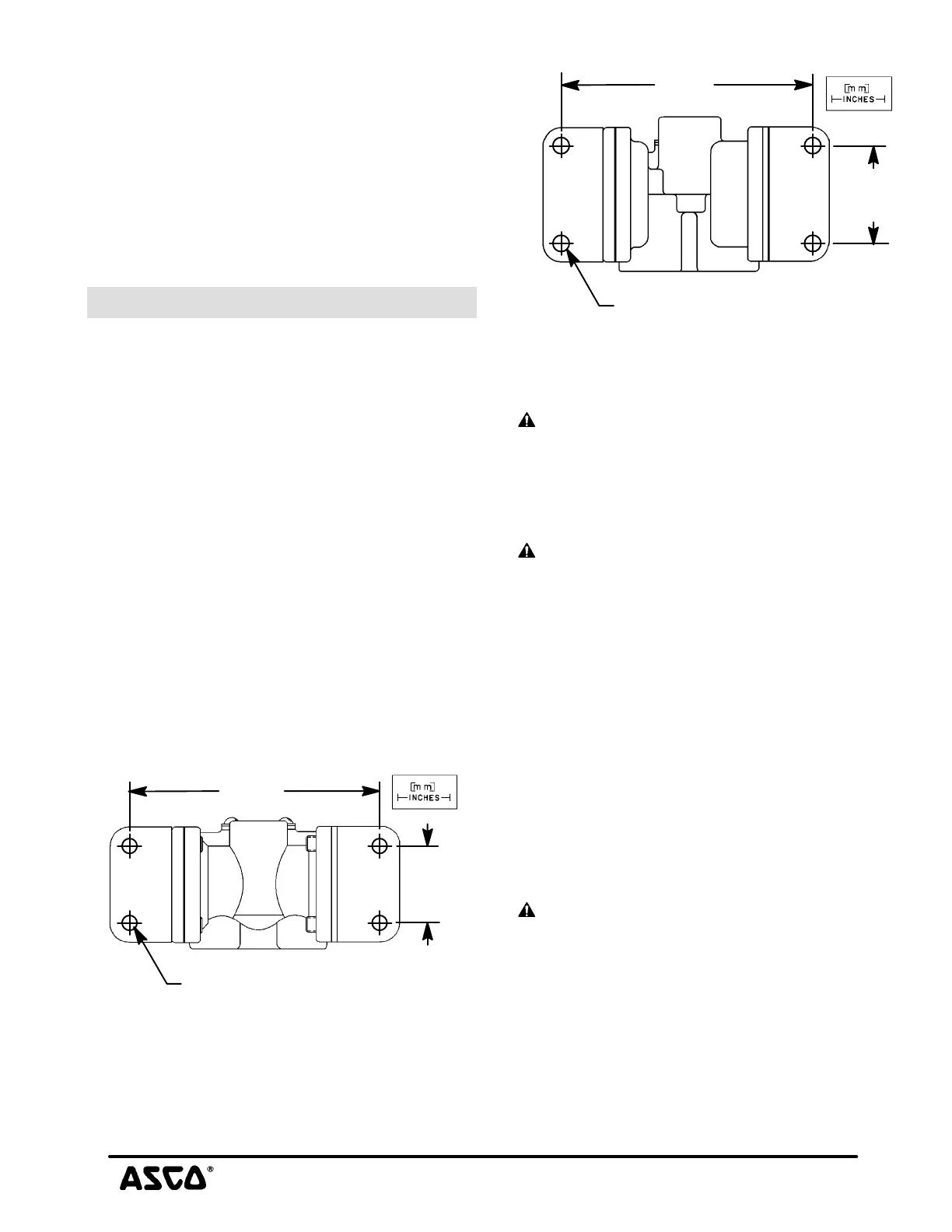
Mounting
Mounting brackets (2) are optional. For valves with a 5/16I
orifice, 1/4I or 3/8I NPT refer to Figure 3; for 5/8I orifice, 3/8I
or 1/2I NPT Figure 4. Check nameplate to determine orifice
sizeāĂandāĂpipeāĂsize.
Figure 3. Mounting dimensions - 5/16I Orifice
4.05
[103]
[32]
1.25
.28 diameter [Ø7,1] 4 places
Figure 4. Mounting dimensions - 5/8I Orifice
4.27
[108]
[42]
1.66
.28 diameter [Ø7,1] 4 places
Piping
There are two exhaust flows in the exhaust mode. There is pilot
exhaust from the top of the solenoid when the valve shifts.
CAUTION: Debris entering 1/8I or 1/4I NPT
connection at top of solenoid may cause valve to
malfunction. Use a muffler to vent to atmosphere or
connect to main exhaust system if the air or inert gas
cannot be exhausted directly to the atmosphere.
Connect piping or tubing to valve according to markings on
valve body. Refer to flow diagrams in OPERATION section.
CAUTION: To avoid damage or accidental
disengagement of cartridge assembly from valve body,
hold cartridge assembly securely by wrenching flats
when installing or removing muffler or piping at top of
solenoid.
Apply pipe compound sparingly to male pipe threads only. If
applied to valve threads, the compound may enter the valve and
cause operational difficulty. Avoid pipe strain by properly
supporting and aligning piping. When tightening the pipe, do
not use valve or solenoid as a lever. Locate wrenches applied
to valve body or piping as close as possible to connection point.
Internal Piloting Mode Only: To insure proper operation of the
valve, the pressure and exhaust piping must be full area without
restriction. A minimum differential pressure (15 psi), as
stamped on the nameplate, must be maintained between
pressure and exhaust at the moment of shifting. Air reservoirs
must have adequate capacity to maintain this minimum
pressure during shifting. To check pressure during shifting,
install a pressure gauge in the pressure piping as close to the
valve as possible.
CAUTION: These solenoid valves are intended for
use on clean dry air or inert gas, filtered to 50
micrometres or better. The dew point of the media should
be at least 10_ C (18_ F) below the minimum temperature
to which any portion of the clean air/inert gas system
could be exposed to prevent freezing. If lubricated air is
used, the lubricants must be compatible with Buna N
elastomers. Diester oils may cause operational
problems. Instrument air in compliance with ANSI/ISA
Standard S7.3-1975 (R1981) exceeds the above
requirements and is, therefore, an acceptable media for
these valves.

 Loading...