Page 2 of 8 (Section 1 of 2) Form No.V6928R3 - Sec. 1
50 Hanover Road, Florham Park, New Jersey 07932 www.ascovalve.com
CHANGING MODE OF OPERATION
WARNING: To prevent the possibility of death,
personal injury or property damage, turn off
electrical power, depressurize valve, and vent
fluid to a safe area before changing mode of
operation.
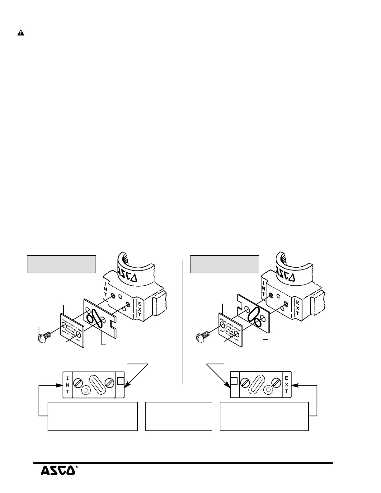
The piloting (Mode of Operation) of the valve is determined by
the positioning of the Support with Flow Gaskets on the side of
the valve body. See Figures 1 & 2 for proper positioning of
Support with Flow Gaskets for internal or external piloting
mode of operation.
Positioning of Support with Flow Gaskets for Internal
Piloting Mode
To change to the Internal Piloting Mode of operation if
previously installed in the external piloting mode or rebuild
after valve disassembly for maintenance, proceed as follows:
1. Install a 1/8I NPT pipe plug in the port marked AUX,
auxiliary pressure connection.
NOTE: To change to internal piloting, remove cover screws (2),
cover and support with large and small flow gaskets. Just turn
over the support 180_ to change piloting and reassemble. To
verify piloting selection, follow rebuild instructions steps below.
2. Refer to views in Figure 1 for proper location and position
of parts for Internal Piloting Mode of operation.
3. Position large and small flow gaskets in support. Large
gasket must be compressed to fit support configuration.
4. Line up support (with flow gaskets) on side wall of valve
body using machine screw holes as a guide. When support
is correctly positioned (as shown in Figure 1.) the letters
INT are visible and letters EXT on opposite side are
covered by the support. Confirm proper alignment with
views in Figure 1. Then replace cover and cover screws.
Torque cover screws evenly to 13 ± 1 in-lbs [1,5 ± 0,1
Nm].
5. Refer to OPERATION - INTERNAL PILOTING MODE
section.
Positioning of Support with Flow Gaskets for External
Piloting Mode
To change to the External Piloting Mode of operation before
valve installation or rebuild after valve disassembly for
maintenance, proceed as follows:
1. Remove a 1/8I NPT pipe plug from auxiliary pressure
connection port marked AUX, using a 5/16I hex key
wrench and connect auxiliary pilot pressure piping.
NOTE: To change to external piloting, remove cover screws
(2), cover and support with large and small flow gaskets (2).
Just turn over the support 180_ to change piloting and
reassemble. To verify piloting selection, follow rebuild
instructions steps below.
2. Refer to views in Figure 2 for proper location and position
of parts for External Piloting Mode of operation.
3. Position large and small flow gaskets in support. Large
gasket must be compressed to fit support configuration.
4. Line up support (with flow gaskets) on side wall of valve
body using machine screw holes as a guide. When support
is correctly positioned (as shown in Figure 2.) the letters
EXT are visible and letters IN T on opposite side are
covered by the support. Confirm proper alignment with
views in Figure 2. Then replace cover and cover screws.
Torque screws evenly to 13 ± 1 in-lbs [1,5 ± 0,1 Nm].
5. Refer to OPERATION - EXTERNAL PILOTING MODE
section.
support with large and
cover with
instructions
screw(2)
support with large and
cover with
instructions
INT" marking shown. This
indicates correct assembly
for internal piloting
EXT" marking shown. This
for external piloting
EXT" mark is covered INT" mark is covered
indicates correct assembly
screw(2)
small flow gaskets
small flow gaskets
Large and small
flow gaskets shown
in phantom
Internal Piloting External Piloting
cover
cover
Figure 1. Positioning of support with Figure 2. Positioning of support with
flow gaskets for internal piloting mode. flow gaskets for external piloting mode.

 Loading...