INSTALLATION GUIDE
9dLD Locator, Version D
9TD 92775EN / 14 December 2020 / Ver. D
6. Installation
6.1 Connect Supply Voltage
The installation cables should be flame resistant and comply with the "VW-1" or the relevant
"60332" standards.
The screw connector is rated for cables with a cross-section of up to 2.5 mm
2
or AWG13.
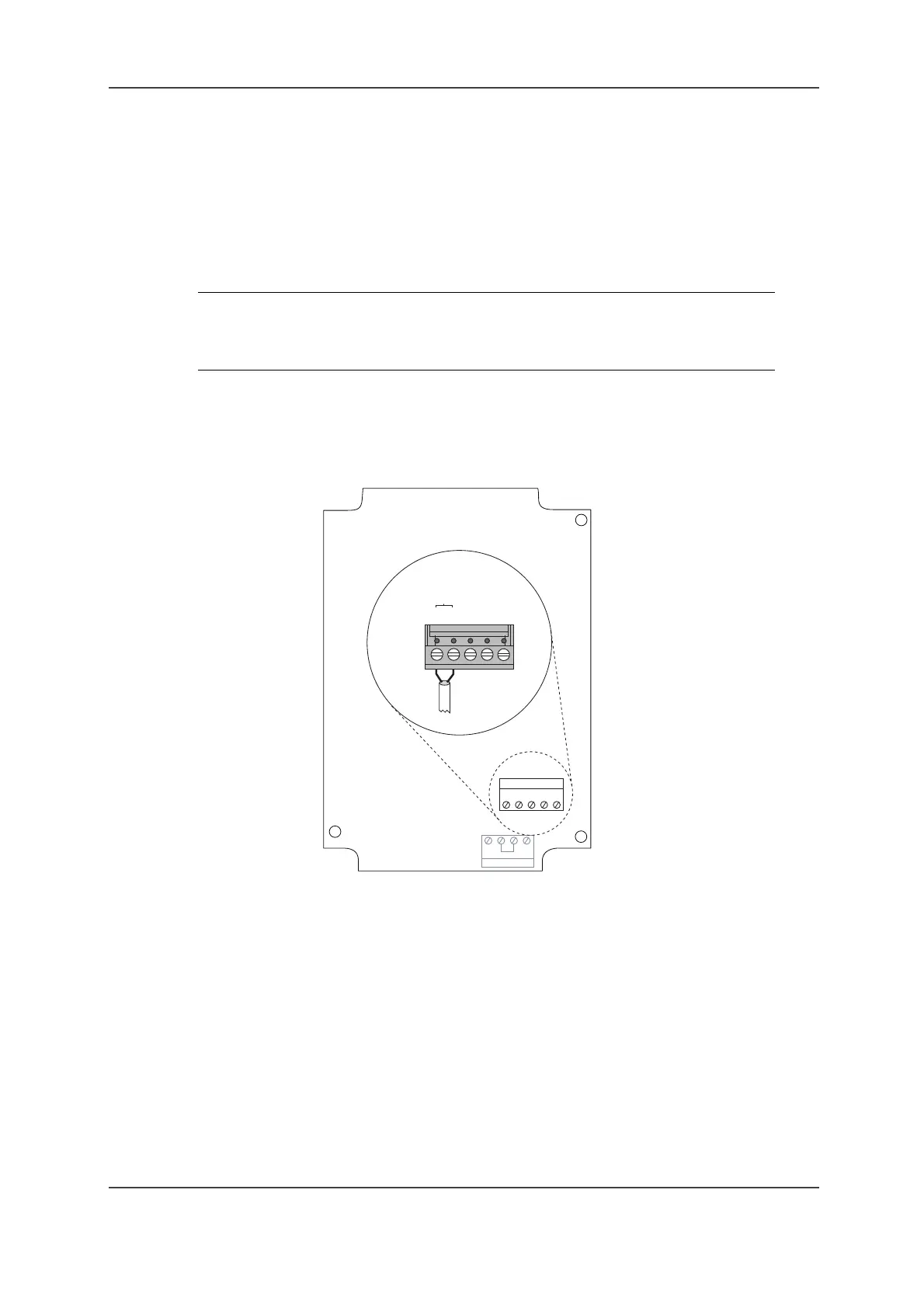
Connect supply voltage (polarity independent) to pin 1 and 2 on J2 as shown in Figure 4.
Connecting supply voltage to 9dLD on page 9.
Figure 4. Connecting supply voltage to 9dLD
IMPORTANT: 9dLD should be protected against currents exceeding 10A. It is the
responsibility of the installer to select cable thickness, cable length
and fuse or other current limiting factors so that a potential failure
condition does not result in overheated cables or other dangers
J2
J1
1
1
4
5
J2
12 - 24 V DC
12345
004