INSTALLATION GUIDE
9dLD Locator, Version D
14TD 92775EN / 14 December 2020 / Ver. D
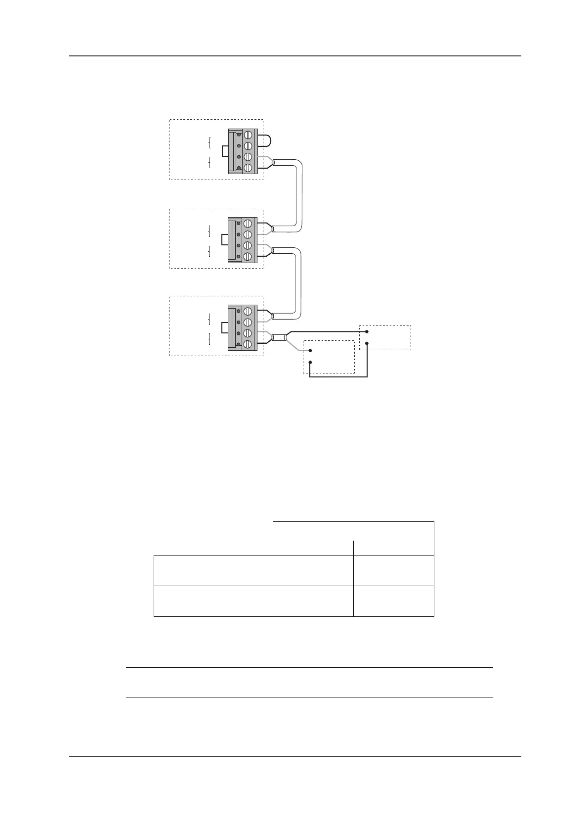
Figure 7. Connection of locator monitoring for three 9dLD units
1 Connect J1:4 on the 9dLD to the positive pole on the external Power Supply (+12 or +24 V
DC). Connect J1:3 on the 9dLD and the negative pole on the external Power Supply to the
Alarm Module (T941AM8 or T941AM32 – see Installation Guide for the Alarm Modules). See
Figure 7. Connection of locator monitoring for three 9dLD units on page 14 above for more
information.
2 The 9dLD monitor outputs can be connected in series. Connect J1:1 on the first 9dLD to J1:4
on the next, and J1:2 on the first to J1:3 on the next. The last unit in the series has to be
strapped. Strap J1:1–2 on the 9dLD.
Depending on the type of Alarm Module and the supply voltage in the monitor loop, the
following number of units can be connected to the same input:
3 Reed relay, SW1, is connected in series with the monitor output. The relay closes when a
magnet is placed near to and parallel to it. The magnet in the 9dLD lid is placed so that the
relay will open in case of any physical damage or tampering.
Supply Voltage
12 V DC 24 V DC
T941AM32
Max no of 9dLDs: 2 9
T941AM8
Max no of 9dLDs: 5 12
NOTE: When the case of the 9dLD is put together, make sure that the reed relay
and the tamper protection magnet are placed opposite each other.
Input on
Alarm
Module
Monitor
out
J1
Monitor
in
1
2
3
4
Power
Supply
+
–
Monitor
out
Monitor
in
1
2
3
4
Monitor
out
Monitor
in
1
2
3
4
J1
J1
007
9dLD
9dLD
9dLD