TD 92232GB
2005-06-15 / Ver.G
Installation Guide
ELISE2
15
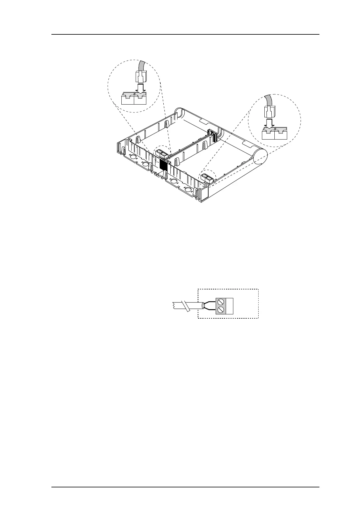
Bus Connection to Modular Jacks
1 The illustration above shows an ELISE2 module placed to the left of another System
900 unit. Connect the bus cable as shown, from connector J12/J13 on the ELISE2
module to the bus connector on the other unit.
Note: Make sure connectors are correctly inserted!
Bus Connection to Screw Terminals
If system bus cable is not used, connections are made with twisted pairs to screw
connector J24.
Figure 9. Connection of System 900 bus.
Other System 900 units are connected to A or B-bus, pin 1 and 2 at screw connector J24.
Note: Observe polarity. Use only twisted pairs for two-wire connections.
ELISE
Other unit
J12 J13
017
J24
2 BUS 2
1 BUS 1
To A or B-bus in other units
within the System 900
018