TD 92232GB
2005-06-15 / Ver.G
Installation Guide
ELISE2
28
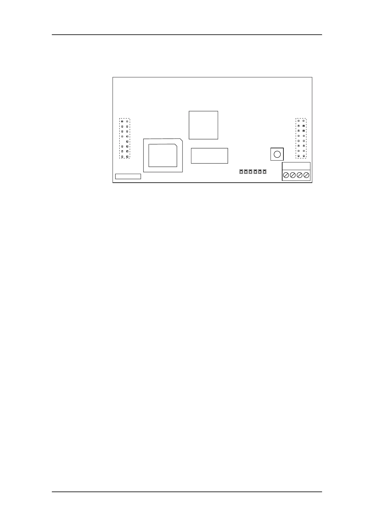
Appendix A: LON Piggy Back Circuit Board (LPB)
Connectors and Jumper Points
Push button
Micro Controllers and others
LEDs
J1 Connection for the teleCARE M LON (only use terminals 1 and 2)
J2 Connector for In System Programming (ISP) of the flash micro controller
J3 Male connector to be put on J9 on ELISE2 circuit board. Pin 12 cut off
J4 Male connector to be put on J10 on ELISE2 circuit board
SW1 For service
IC1 Flash memory
IC3 Neuron micro controller
IC9 PIC flash micro controller
LED1 LON Rx
LED2 LON Tx
LED3 See table for LED3 in Status Indication of LPB on page 29
LED4 Rx data transfer
LED5 Tx data transfer
LED6 See table for LED6 in Status Indication of LPB on page 29
IC1
IC3
IC9
J1
J2
J3
J4
SW1
LED
1
2
3456
029