Installation of the Base Station
INSTALLATION GUIDE
IP-DECT Base Station and IP-DECT Gateway
3.2.6 Secure the Cable
For safety reasons secure the base station cable to a convenient point at about 30 cm from the base station.
If for some reason the base station drops, it is secured by the cable.
3.2.7 Pinning
1. Cut the cable to the correct length and connect the cable to a RJ45 modular jack.
2. For information on the pinning of the data jack see the following:
− IPBS, Pin the IPBS Cable.
− BS3x0 and DB1, Pin the BS3x0/DB1 Cable.
Do not plug the connector in the base station yet!
Since the distance between the base station and the wall is limited, a RJ45 modular jack without
cable retention must be used.
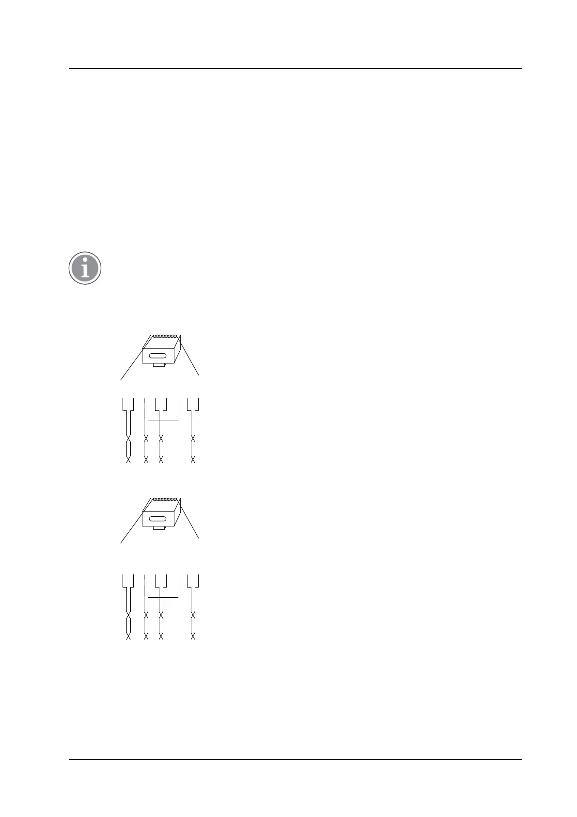
Pin the IPBS Cable
Figure 12. Connector pinning of the LAN/PoE connector, power feed over the spare cable pairs.
RJ45
modular jack
Tx
Tx
Rx
Pwr
Pwr
Rx
Pwr
Pwr
Pwr = Power pairs
Rx = Reciever data pair
Tx = Transmitter data pair
014
1 5432 6 7 8
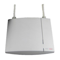
Figure 13. Connector pinning of the LAN/PoE connector, power feed over the Rx/Tx data cable pairs.
RJ45
modular jack
Tx/Pwr
Tx/Pwr
Rx/Pwr
Spare
Spare
Rx/Pwr
Spare
Spare
NC
=
Not Connected
Rx/Pwr
=
Reciever & power pair
Tx/Pwr = Transmitter & power pair
015
1 5432 6 7 8
21
TD 92989EN / 25 January 2021 / Ver. E