Installation of the IPBL
INSTALLATION GUIDE
IP-DECT Base Station and IP-DECT Gateway
4.2.2 RFP Cable
The RFP cable connects the IPBL with the RFPs. The maximum cable length between IPBL and a single RFP
must not exceed 1500 meters.
Ensure that during the installation, each RFP is given an extra length (5-10 metres) of cable
because it is possible that it will have to be moved for one reason or another.
1. Cut the cable to the correct length.
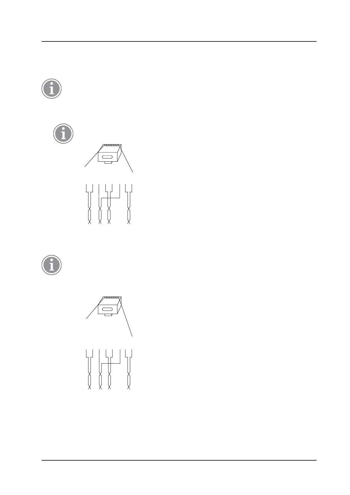
2. Connect the cable to a RJ45 modular jack. For information on the pinning, see below.
If local power supply is used for the RFP, the EPP cable pairs must NOT be connected.
RJ45
modular jack
EPP -b
EPP -a
SC1 -a
SC0 -a
SC0 -b
SC1 -b
NC
NC
NC= Not Connected
EPP= Express Power pairs
SC = Data pair lead
028
1 5432 6 7 8
3. Label the cable.
4.2.3 LAN Cable
The TX/RX crossover/straight cable feature does not work in the IPBL. It must be a straight cable
between the IPBL and the switch port.
1. Cut the cable to the correct length.
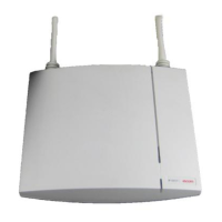
2. Connect the cable to a RJ45 modular jack. For information on the pinning, see below.
RJ45
modular jack
Ethernet A +
Ethernet A -
Ethernet B +
NC
NC
Ethernet B -
NC
NC
NC = Not Connected
029
1 5432 6 7 8
3. Label the cable.
4.3 Power the IPBL
The IPBL power supply connectors are located at the rear. The power supply feeds both the IPBL and the
connected RFPs. There are two alternatives to power the IPBL:
27
TD 92989EN / 25 January 2021 / Ver. E