INSTALLATION GUIDE
IP-DECT Base Station and IP-DECT Gateway Description
2.3.1 Overview
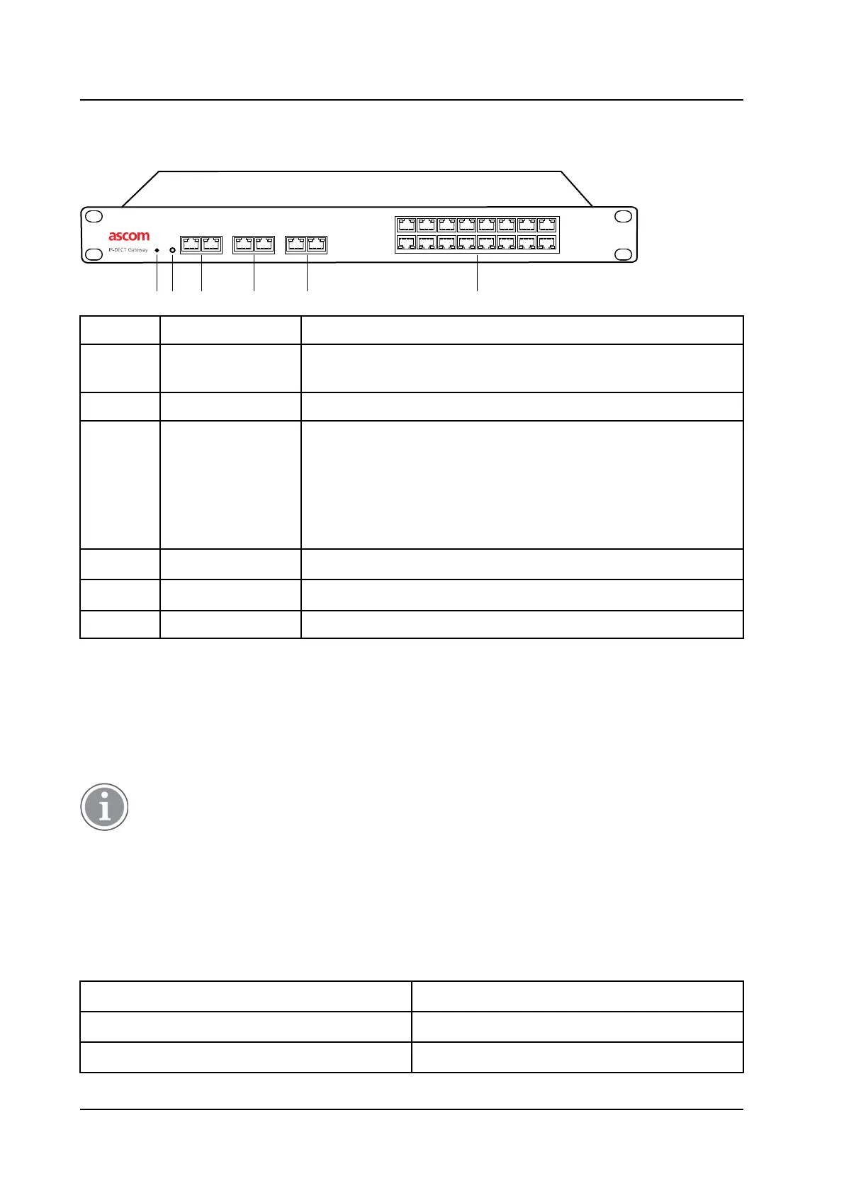
Figure 4. Overview of the IPBL
lan synchronization reference
1 2 ring in ring out in out
base station 01 02 03 04 05 06 07 08
09 10 11 12 13 14 15 16
006
1 2 3 4 5 6
Pos. Name Function
1 Reset Resets the IPBL. For information on how to use the reset button, see
the applicable Installation and Operation Manual for the IPBL.
2 Status LED Indicates the status on the IPBL.
3 Lan 10BASE-T/100BASE-T Ethernet interface.
LAN1 port must be used in the IP-DECT system (LAN2 port is for
administration only).
Note: This is not applicable when RSTP is used. For information about
RSTP, see the applicable Installation and Operation Manual for the
device.
4 Synchronization Sync ring in and sync ring out interfaces.
5 Reference Reference sync in and reference sync out interfaces.
6 Base station 01-16 ISDN U
PN
DECT base station interfaces.
2.3.2 Power Supply
The power supply are located at the rear of the IPBL. The IPBL can be powered using the following
alternatives:
• 110/230 VAC (only IPBL IP-DECT Gateway VAC/VDC)
• 48 VDC
For more information, see 4.3 Power the IPBL, page 27.
Software
The software in the IPBL can be updated by downloading new software without disconnecting the
equipment. The new software is stored in flash memory. For information on how to update the software in
the IPBL, see the applicable Installation and Operation Manual for the IPBL.
2.3.3 LED indication
Status LED Description
Not lit Not powered, status is not defined.
Flashing slow green When pressing the reset button.
TD 92989EN / 25 January 2021 / Ver. E
8