EasyManua.ls Logo

ascon A5LCX 10 C - User Manual

ascon A5LCX 10 C
137 pages
To Next Page IconTo Next Page
Loading...
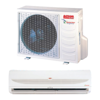
DC Inverter Single Split
A5LCX - 2007
Models:
A5LCX 10 C/CR
A5LCX 15 C/CR
A5LCX 20 C/CR
A5LCX 25 C/CR

Questions and Answers:

ascon A5LCX 10 C Specifications

General IconGeneral
Brandascon
ModelA5LCX 10 C
CategoryAir Conditioner
LanguageEnglish

Summary

1. Nomenclature

2. FEATURES

Refrigerant Circuit Diagrams

Controllers

G12 REMOTE CONTROLLER

Details the functions and operation of the G12 remote controller.

SLM Controller Operating Instructions

SLM AC-5300 (OPTIONAL)

Operating instructions for the SLM AC-5300 controller.

Installation Diagram

1. Selection Of Location And Space

Wall Mounted

Specific requirements for wall-mounted indoor unit installation.

2. Drilling Holes And Mounting Plate Installation

3. Indoor Unit Preparation

4. Mounting Indoor Unit

5. Water Drainage Piping

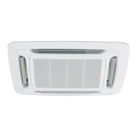
Ceiling Cassette

Unit Installation

Steps and considerations for installing the ceiling cassette unit.

Unit Hanging

Drain Piping Work

Drain Test

Panel Installation

Ceiling Convertible

Preliminary Site Survey

Site survey requirements for ceiling convertible units.

Standard Mounting

Guidelines for standard mounting procedures.

Under ceiling type

Floor standing type

Under Ceiling Installation

Install the Suspension Bolts

Steps for installing suspension bolts for under-ceiling mounting.

Install the Indoor Unit

Steps for mounting the indoor unit.

Floor standing installation

Piping and Drain Hose Installation

Under Ceiling Type

Piping and drain hose installation for under-ceiling units.

Floor standing type

Piping and drain hose installation for floor-standing units.

How to Install the Drain Hose

Ceiling Concealed

Preliminary Survey

Site survey requirements for ceiling concealed units.

Outdoor Unit

6. Installation Clearances

8. Wiring

9. Refrigerant Piping

A) Maximum Pipe Length and Maximum Number of Bends

Guidelines for refrigerant pipe length and bends.

B) Flare Connection

Procedure for connecting refrigerant pipes using flare fittings.

10. Special Precaution For R410 A

4) Check list before installation;servicing

Checklist for tools and items needed for R410A installation/servicing.

5) Handling and installation guidelines

Guidelines for safe handling and installation of R410A systems.

General Data - Cooling Only

General Data - Heatpump

General Data - Cooling Only (With Torque Control)

General Data - Cooling

Components Data - Cooling Only

Components Data - Heatpump

Components Data - Heatpump (With Torque Control)

5. DIMENSIONAL DATA

Outdoor Unit

Dimensional data for outdoor units (A5LCX 10/15 C/CR).

Indoor Unit

Outdoor Unit

6. ELECTRICAL DATA

INDOOR MOTOR

Electrical data for indoor motors.

OUTDOOR MOTOR

Electrical data for outdoor motors.

COMPRESSOR

Electrical data for the compressor.

INDOOR MOTOR

OUTDOOR MOTOR

Electrical data for outdoor motors.

COMPRESSOR

Electrical data for the compressor.

7. WIRING DIAGRAMS

Outdoor Unit

Wiring diagram for the outdoor unit.

MODEL: A5 CKX 20;25 A;AR c;w A5 LCX 20;25 C;CR

MODEL: A5 CMX 20;25 E;ER c;w A5 LCX 20;25 C;CR

MODEL: A5 CCX 10;15 C;CR c;w A5 LCX 10;15 C;CR

MODEL: A5 CCX 20;25 C;CR c;w A5 LCX 20;25 C;CR

8. SERVICING AND MAINTENANCE

Service Parts

Lists parts requiring maintenance and their procedures.

Indoor Air Filters

Procedure and period for cleaning indoor air filters.

Indoor Unit

Procedure and period for cleaning the indoor unit.

Indoor;Outdoor Coil

Procedure for cleaning coils and removing obstacles.

Electrical

Procedure for checking electrical components and connections.

Compressor

Maintenance requirements for the compressor, including leak checks.

9. TROUBLESHOOTING

Fault conditions

Lists common fault conditions of the air conditioner unit.

Possible causes; corrective actions

Provides possible causes and corrective actions for faults.

Diagnostic Guidelines

By means of pressure reading:

Guidelines for diagnosing issues using refrigerant pressure readings.

By means of diagnostic flow chart:

i) Diagnosis of Electric Circuit

Flowchart for diagnosing electrical circuit faults.

ii ) Diagnosis of Refrigerant Circuit; Application

Compressor Stopped Troubleshooting Instructions

Keep the Main Power Supply ON

Important safety instruction before opening panels.

DO NOT TOUCH ANY OF THE WIRES INSIDE THE UNIT!

Critical safety warning regarding electrical components.

Count the number of blinks indicated by the LED

Guide to interpreting LED blink codes for troubleshooting.

Blink

Table of fault indications and corrective actions based on LED blinks.

Indicator Lights

Cooling; Heatpump Unit

Explains LED indicators for normal and fault conditions.

2 Normal Running Mode Condition

10. EXPLODED VIEW AND PARTS LIST

Indoor Unit

Exploded view and parts list for indoor units.

MODEL: A5 WMX 20;25 G;GR

MODEL: A5 CKX 20;25 A;AR

MODEL: A5 CKX 10;15;20 C;CR

MODEL: A5 CMX 15;20;25 E;ER

MODEL: A5 CCX 10 C;CR

MODEL: A5 CCX 15;20;25 C;CR

MODEL: A5 LCX 10; 15 C;CR

MODEL: A5 LCX 20; 25 C;CR

Related product manuals