Home
ASEM
Network Router
Ubiquity RK11
ASEM Ubiquity RK11 User Manual
4
of 1
of 1 rating
78 pages
Give review
Manual
Specs
To Next Page
To Next Page
To Previous Page
To Previous Page
Loading...
33
Ubiquity
Router family - User
’s
guide
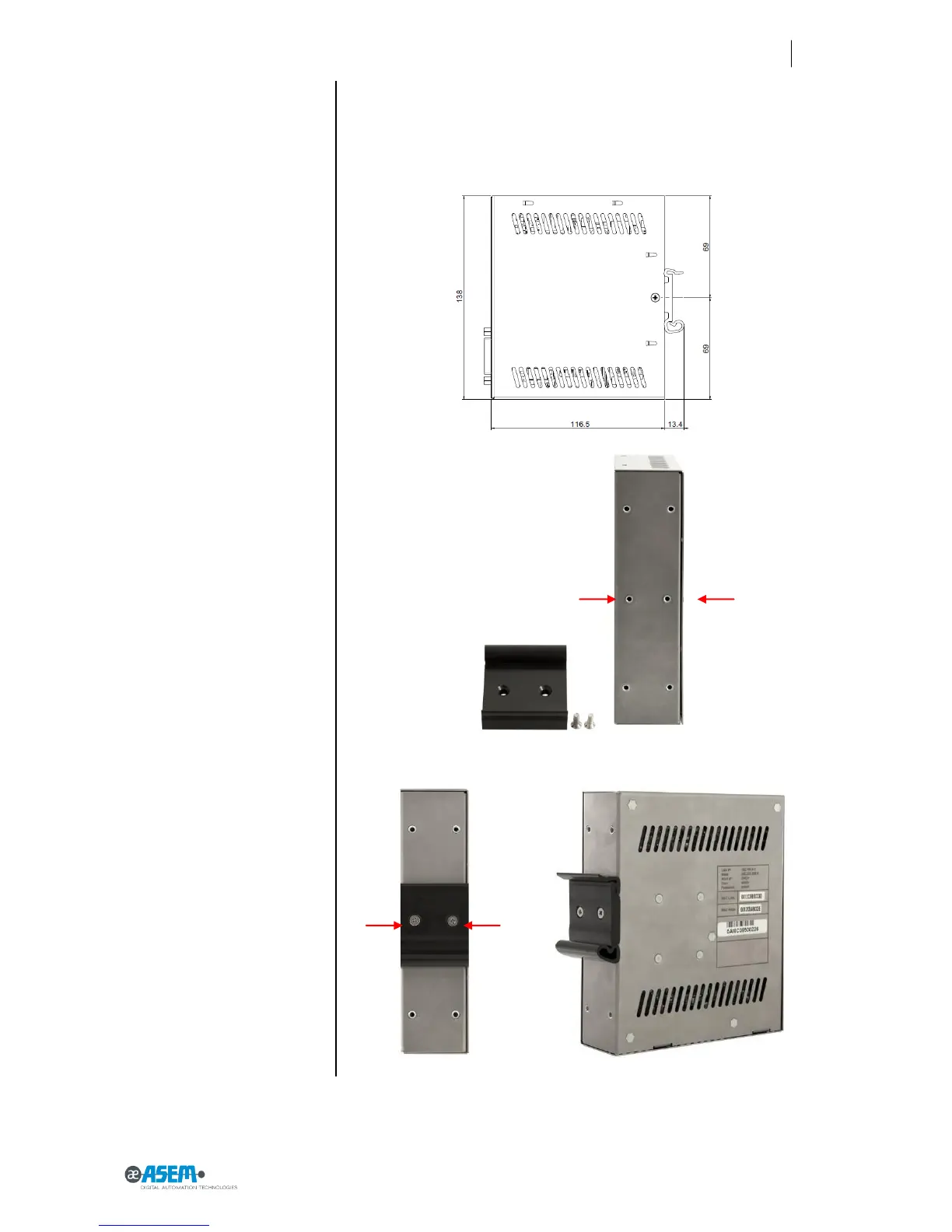
Figure
22
Wall moun
ting installatio
n procedure
Figure
23
Wall moun
ting installatio
n procedure
Figure
24
Wall moun
ting installatio
n procedure
3.6.2
DIN guide mounting installation procedure
The system can be installed
on a
DIN guide as follow
s:
In
stall the DIN hook as illu
strated in
the picture.
38
40
Table of Contents
Table of Contents
3
Section 1
7
General Notes
8
Instructions on Disposal
8
Trademarks
8
Description of Safety Symbols
9
Basic Knowledge Required
10
Figures
10
Proper Use of the Product
10
Purpose of the User's Guide
10
Qualified Personnel
10
The Manual Is a Part of the System
10
Safety Instructions
11
Installation According to the Instructions
11
Hazardous Areas
11
Working on the Control Cabinet
11
Scope of the Operating Instructions
11
Applicable Standard
12
Notes about Usage
12
1 Preliminary Information
7
Section 2
13
2 Description
13
Product Description
14
Key Features
14
Package
15
Front View RK10
16
Figure 1 RK10
16
Front View RM10
18
Front View RK11
20
Figure 2 RK11
20
Front View RM11
22
Figure 3 RM11
22
UP View
24
Figure 4 RK10
24
Right View
25
Figure 5 RK10
25
Left View
26
Rear View (RK11/RK11 ET - RM11 / RM11 ET)
26
Figure 6 RK10
26
Figure 7 RK11/RM11
26
Rear View (RK10/RK10 ET-RM10/RM10 ET)
27
Figure 8 RK10
27
Labels
28
Figure 9 RK10
28
Figure 10 RK10
29
Antenna
30
Figure 11 RK11
30
Figure 12 Pentaband Stilo Antenna
30
Figure 13 Pentaband Wall-Mount Antenna
31
Figure 14 Pentaband Outdor Antenna
32
Section 3
33
3 Installation and Connection
33
Preparation for Installation
34
Select the Mounting Location
34
Checking the Package Contents
34
Checking the Operating Conditions
34
Mounting Position
34
Damage Due to Overheating
35
Preparing the Mounting
35
Mounting the Device
36
Wall Mounting Installation Procedure
36
Figure 15 Wall Mounting Installation Procedure
36
Figure 16 Wall Mounting Installation Procedure
36
Figure 17 Wall Mounting Installation Procedure
37
Figure 18 Wall Mounting Installation Procedure
37
Figure 19 Wall Mounting Installation Procedure
37
Figure 20 Wall Mounting Installation Procedure
37
Figure 21 Wall Mounting Installation Procedure
38
DIN Guide Mounting Installation Procedure
39
Figure 22 Wall Mounting Installation Procedure
39
Figure 23 Wall Mounting Installation Procedure
39
Figure 24 Wall Mounting Installation Procedure
39
Figure 25 Wall Mounting Installation Procedure
40
Figure 26 Wall Mounting Installation Procedure
40
Figure 27 Wall Mounting Installation Procedure
41
SIM Installation
42
Figure 28 SIM Card Installation
42
Figure 29 SIM Card Insertion
42
Figure 30 SIM Card Insertion
43
Figure 31 SIM Card Inserted (Datail)
43
Antenna Installation
44
Figure 32 Pentaband Stilo Antenna Installation
44
Figure 33 Pentaband Stilo Antenna Installation
44
Figure 34 Pentaband Wall-Mount Antenna Installation
45
Figure 35 Pentaband Outdor Antenna Installation
45
Figure 36 Pentaband Outdor Antenna Installation
46
Connecting the Device
47
Notes on Connection
47
Grounding and Bonding
47
Power Supply Connection
47
Figure 37 Power Supply Connection Detail
47
Connecting the Ethernet Ports
48
Figure 38 Power Supply Connection Detail
48
Figure 39 Ethernet Connection Detail
48
Switching on and Testing the Ubiquity Router Device Device
49
Figure 40 Power Supply Connection Detail
49
Connecting the Serial Port
50
Connecting to MPI or PPI Networks
50
Figure 41 DB9 Connector Detail
50
Figure 42 Adapters Detail
51
Connecting Digital I/O
52
IN0 - WAN Connection Enabling Security Key
52
IN1 - Reset Input
52
Figure 43 IN0 - WAN Connection Enabling Security Key Example
52
Figure 44 IN1 - Reset Input
52
OUT0 - WAN Connection Enabled Signalling
53
OUT0 - Remote Assistance Service Running
53
Figure 45 OUT0 - WAN Connection Enabling Signalling Example
53
Figure 46 OUT0 - WAN Connection Enabling Signalling Example
53
Figure 47 OUT0 - Remote Assistance Service Running Example
53
Figure 48 OUT0 - Remote Assistance Service Running Example
53
Section 4
55
4 Commissioning
55
Configuring
56
Ubiquity Router RM Models
56
5 Maintenance and Care
59
Maintaining & Cleaning
60
Backup Battery Replacement (CR1220 3V)
60
Figure 49 Backup Battery Replacement
60
Figure 50 Backup Battery Replacement
60
Figure 51 Backup Battery Replacement
61
Figure 52 Backup Battery Replacement
61
Figure 53 Backup Battery Replacement
62
Figure 54 Backup Battery Replacement
62
Backup and Restore
63
Updating the System
63
Figure 55 Backup Battery Detail
63
Figure 56 SIM Card Socket
63
Technical Support & Repairs
64
Recycling and Disposal
64
Section 5
59
Section 6
65
6 Technical Specifications
65
Technical Specifications
66
Certificates and Approvals
69
Dimension Drawings
70
Figure 57 Dimensions
70
Panel Antenna Drawing Dimensions
72
Wall Mount Antenna Drawing Dimensions
73
Outdoor Panel Antenna Drawing Dimensions
74
Ports PINOUT
75
COM1 - DB15M Serial
75
Digital In/Out
75
DC Input
76
DC Input
77
4
Based on 1 rating
Ask a question
Give review
Questions and Answers:
Need help?
Do you have a question about the ASEM Ubiquity RK11 and is the answer not in the manual?
Ask a question
ASEM Ubiquity RK11 Specifications
General
Brand
ASEM
Model
Ubiquity RK11
Category
Network Router
Language
English
Related product manuals
ASEM Ubiquity RK10
78 pages
ASEM Ubiquity RM10
78 pages
ASEM Ubiquity RM11
78 pages
 Loading...