V2000 – Installation Guide
U-0623-0291.docx – Issue: 04 complete, approved
Page 16 of 40
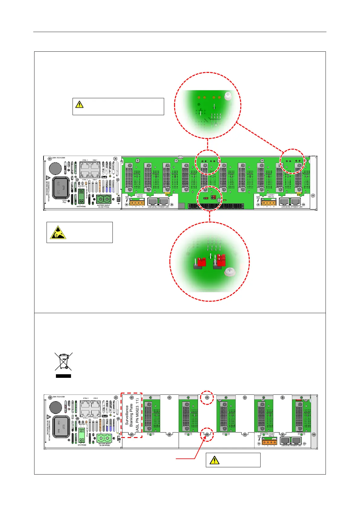
c. 2 x V2000-STBY Interface Cards fitted:
10. Cover all unused LSZDC Interface Card slots with a V2000 Surveillance Blanking Plate as specified
in your system design.
The example below shows a blanking plate covering slots 2, 4, 6, 8 and 10.
Any blanking plates removed from the V2000 as part of the installation process ideally
should be recycled as metal or otherwise responsibly disposed of by following WEEE
protocols.
LINKS NOT FITTED
(Top rear panel bar and bottom middle blanking plate not shown for clarity.)
Observe precautions for
handling electrostatic
sensitive devices.
LINKS NOT FITTED
Ensure that all standby links are NOT FITTED.
If fitted, amplifiers may get damaged when a
standby amplifier switches over.
M3 (6 mm)
Pozidriv
pan head
screw
Blanking Plate
Secure the blanking plate
using 2 x screws.
steel screws.