V2000 – Installation Guide
U-0623-0291.docx – Issue: 04 complete, approved
Page 9 of 40
5 Installation
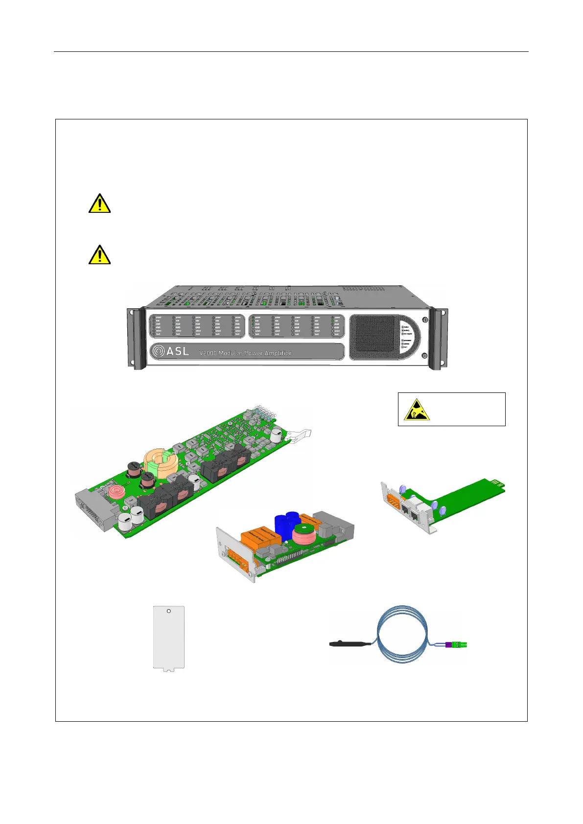
1. Place the mainframe, amplifier modules, interface cards and the required connectors and fixings on
the floor or on a sturdy table as close as possible to the rack.
The main components are shown in the illustration below. Note that types and quantities depend on
the system design of the specific location.
Do not use the handles to lift or carry the mainframe. The handles are designed for sliding
the unit into and out of the equipment rack, and not to support its weight.
Use the underside edges of the mainframe to lift and carry it.
Do not connect cables or other wiring to the V2000 until instructed.
Observe precautions for
handling electrostatic
sensitive devices.
D500 /D150 Amplifier Module
(Illustrations not to scale. Only main components shown, screws,
connectors and cable omitted for clarity.)
(Blanking plates fitted to
the rear panel.)
(Front panel shown fitted, but normally supplied loose.)
Surveillance Blanking Plate
(Handles supplied fitted.)
Thermistor Assembly Cable