V2000 – Installation Guide
U-0623-0291.docx – Issue: 04 complete, approved
Page 25 of 40
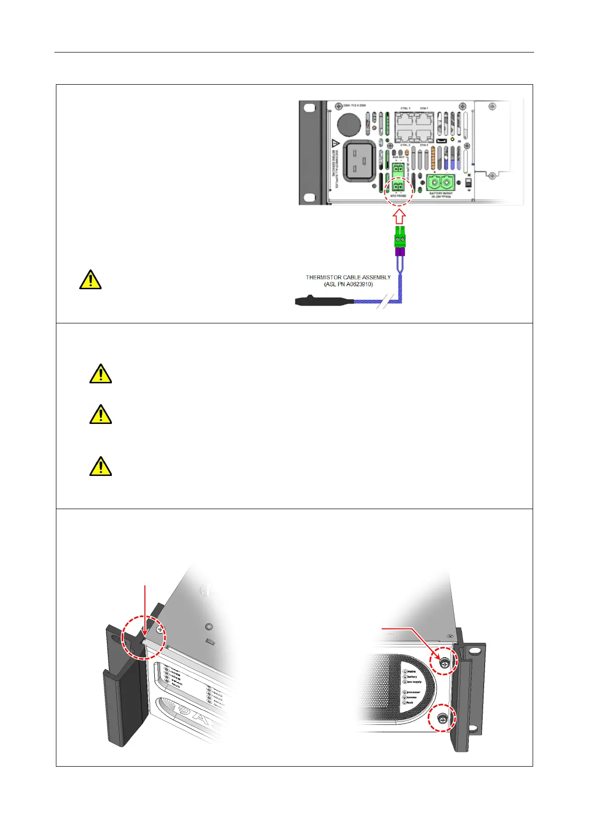
22. If battery power supply is used, connect the
thermistor cable assembly to the real panel
connector NTC PROBE.
Note that the thermistor cable assembly is
supplied with the BDIST-V2000.
Ensure the thermistor probe is positioned
close to the batteries (fixed to the battery
tray or similar).
Adjust the cable length as required by
looping the cable and securing the loop
portion with standard cable ties.
Take care not to plug the thermistor
cable assembly into the top
AUX OUT socket.
23. Commission the mainframe by following the instructions on the V2000 User’s Manual
The power supply to the unit should remain isolated until system commissioning.
Follow the instructions on the V2000 Quick Start Guide to power up the unit.
The Ethernet cables should not be connected to the V2000 until system commissioning as
all V2000 units are supplied with same IP settings (factory default).
Follow the instructions on the V2000 User’s Manual to configure the unit’s IP address.
Do not fit the V2000 front panel until connections to the mainframe and peripherals have
been made and the system commissioned and tested.
Once the front panel is fitted, the power ON/OFF switches will not be accessible.
24. Fit the V2000 front panel by sliding its left end under the left handle, and fixing its right end using the
Pozidriv screw
Left end under the handle