1716
11.4 BACKREST ANGLE ADJUSTMENT
1. Using the Allen key supplied, loosen the screws on either side of
the backrest plate.
2. Reposition backrest into the desired position and fasten screws
in place.
11.5 FRONT CASTOR HEIGHT ADJUSTMENT
1. Using the Allen key supplied, loosen the bolts and remove the
centre pin.
2. Reposition to the desired height, reposition centre pin and fasten
with bolts.
NOTE: Ensure the front castors are located in symmetrical positions
on both sides of the chair to maintain stability.
11.6 FRONT CASTOR FORK ANGLE ADJUSTMENT
1. Using the Allen key supplied, remove both mounting screws.
2. Fork can be re positioned to 4 pre-determined angle and fasten
with screws.
NOTE: Ensure the front castors are located in symmetrical positions
on both sides of the chair to maintain stability.
11.7 FOOTREST HEIGHT ADJUSTMENT
1. Using the Allen key supplied, loosen the bolt on the side of
the footrest.
2. Reposition the height of the footrest and fasten in place with
the bolt.
11.8 FOOTREST ANGLE ADJUSTMENT
1. Using the allen key supplied, loosen the bolt on the side of
the footrest.
2. Reposition the angle of the footrest and fasten in place with
the bolt.
Aspire Evoke 2 and Evoke 2 JNR Manual Wheelchairs are compatible with a large range of accessories
to improve product performance.
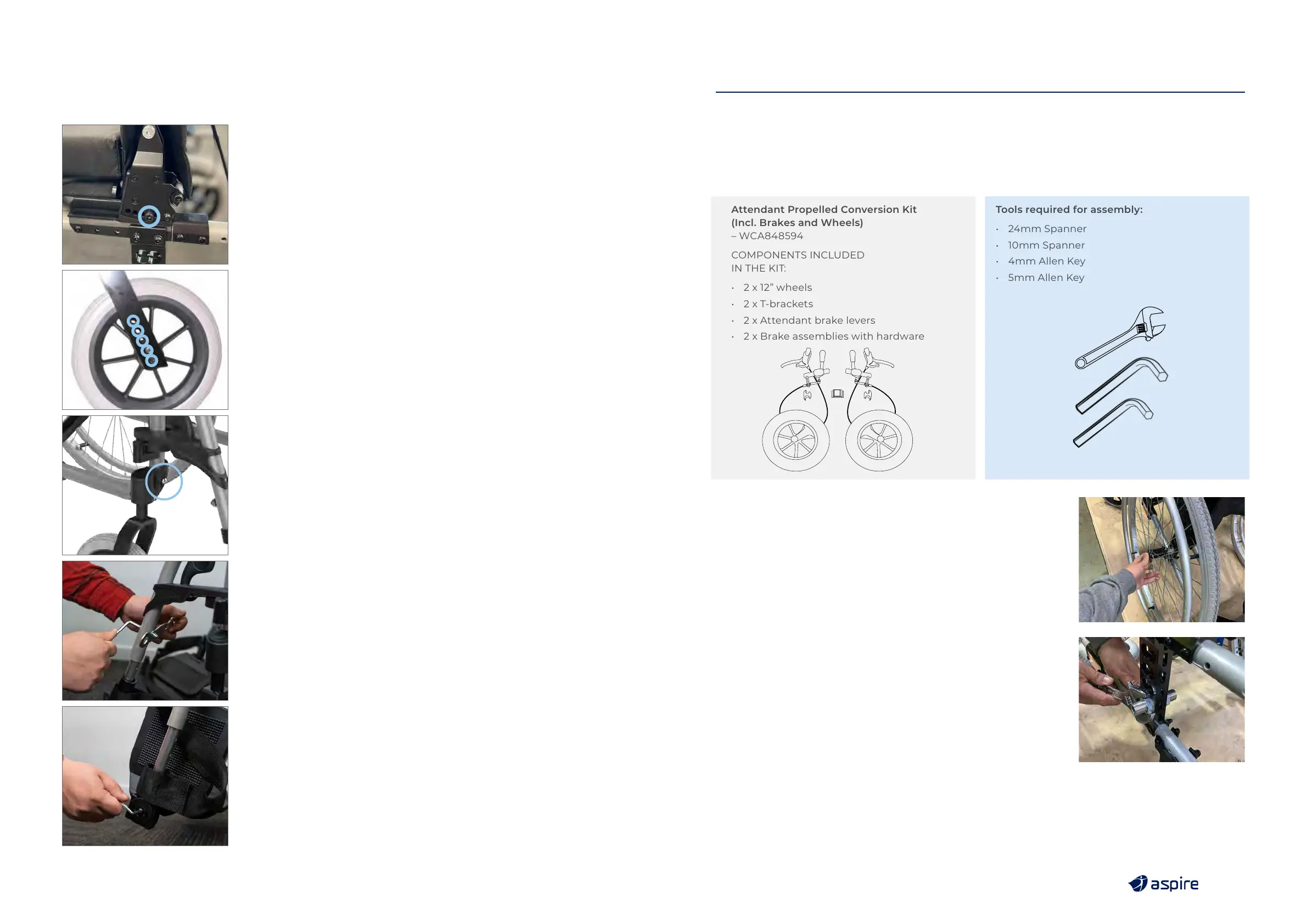
12.1 ATTENDANT PROPELLED CONVERSION KIT
Attendant Propelled Conversion Kit
(Incl. Brakes and Wheels)
– WCA848594
COMPONENTS INCLUDED
IN THE KIT:
• 2 x 12” wheels
• 2 x T-brackets
• 2 x Attendant brake levers
• 2 x Brake assemblies with hardware
Tools required for assembly:
• 24mm Spanner
• 10mm Spanner
• 4mm Allen Key
• 5mm Allen Key
1. Remove the 24” wheel
a. Press the axle cap in to release the axle and wheel from
the wheelchair
2. Remove the Axle receiver for the 24” wheels from the upright
mounting bracket.
a. Use the 24mm spanner to unscrew the nut on both sides
b. Remove the axle receiver
c. Keep it with the 24” wheels, axle, and axle receiver
in a safe place (should you wish to convert the wheelchair
to Self Propelled again in future)
12. ACCESSORIES