EasyManua.ls Logo

Assa Abloy Cabinet Lock Series User Manual

Assa Abloy Cabinet Lock Series
12 pages
To Next Page IconTo Next Page
Page #1 background imageLoading...
Page #1 background image
1 Part Number 3085006.001, Rev 3
HES K200-622
Cabinet Lock Series
Installation Instructions
Machine
screw with
washer
Package Contents
Strike Plate
6-32 screws
2X
5/16”
1”
1-5/8”
1-1/4”
1-3/4”
2-1/2”
2X
1X
3X
2X
2X
0-80x½”
2-56x3/8”
2-56x1-1/4”
Key Override Paddle
2X
1X
1X
6 x 1/2”
3X
1-7/8”
2X
Recommended Tools
Optional:
Cam lock for key override
Double door bracket
Lock Body
Drill, Drill bits: 5/32”, 1/2”
Approved Credential:
i.e. iCLASS or Prox ID card
Phillips drivers P0, P2
Pencil, Wire Stripper
Voltage: 1224 VDC ±10% (Power Supply not provided)
HES K200-622 (Reader) Current Consumption:
12 VDC: 38 mA peak for Red and Green LED only
226 mA peak for Red and Green LED and Motor Drive
24 VDC: 17 mA peak for Red and Green LED only
118 mA peak for Red and Green LED and Motor Drive
Operating Temperature: -10C to 50C
Holding Force: 150 lbs
Lock Reader
Specifications
Mounting
Template
Interface Cable, Lock Side
Interface Cable,
System Side
Cam
Question and Answer IconNeed help?

Do you have a question about the Assa Abloy Cabinet Lock Series and is the answer not in the manual?

Assa Abloy Cabinet Lock Series Specifications

General IconGeneral
BrandASSA ABLOY
CategoryLocks
SeriesCabinet Lock Series
TypeCabinet Lock
MaterialZinc Alloy
ApplicationCabinets, Drawers
FinishNickel, Brass, Chrome
Keying OptionsKeyed alike, keyed different
InstallationSurface Mount
Security LevelMedium

Summary

Package Contents

Recommended Tools

Specifications

System Overview

Mounting the Lock

Establish Latch Centerline

Establish the horizontal centerline of the latch for lock body positioning.

Transfer Cabinet Wall Location

Transfer the location of the inside wall of the cabinet to the door.

Use Lock/Reader Template

Place and use the Lock/Reader Template to mark drill points.

Install Shaft Extension

Install Key Override Paddle

Prepare Key Override Door

Install Antenna/Reader

Install Lock Body

Secure Lock Body

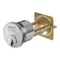
Attach the lock body to the antenna/reader using mount screws.

Connect Antenna/Reader Wire

Attaching the Wiring

Connect Interface Cables

Connect the Lock Side Interface Cable and System Side Interface Cable.

Power Cabling Guidelines

Install Strike Plate

Install Single Door Strike Plate

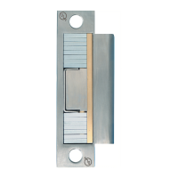
Install the single door strike plate over pilot holes and tighten screws.

Install Double Door Strike Plate

Install the double-door strike plate bracket and strike plate.

Related product manuals