3
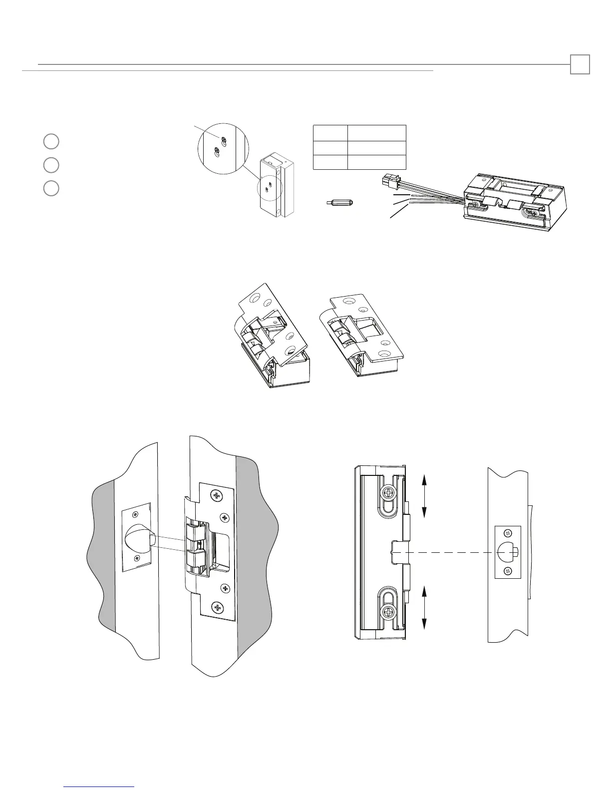
Installation Diagrams
LBM WIRING
White
Orange Normally Open
Green Normally Closed
Common
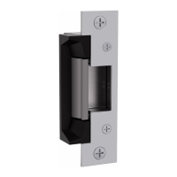
Diagram 4. Latchbolt MonitorDiagram 3: Fail Safe to Fail Secure
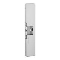
Diagram 5: Faceplate Installation
a
b
c
Screws are loosened, but
not removed
Screws are moved to the Fail Safe
position as shown
Screws are tightened
Diagram 7. Vertical Adjustability
Diagram 6. Vertical Alignment
Fail Safe*
Centerline
*Fire rating only applies to Fail
Secure units. Conversion to Fail
Safe negates fire rating on 8300
White
Orange
Green
 Loading...