04/30/16
1-800-810-WIRE • www.sargentlock.com • A8011H 15
Copyright © 2016, Sargent Manufacturing Company, an ASSA ABLOY Group company. All rights reserved.
Reproductions in whole or in part without express written permission of Sargent Manufacturing Company is prohibited.
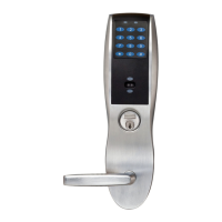
Passport 1000 P2 Mortise Lock
Fig. 10
B
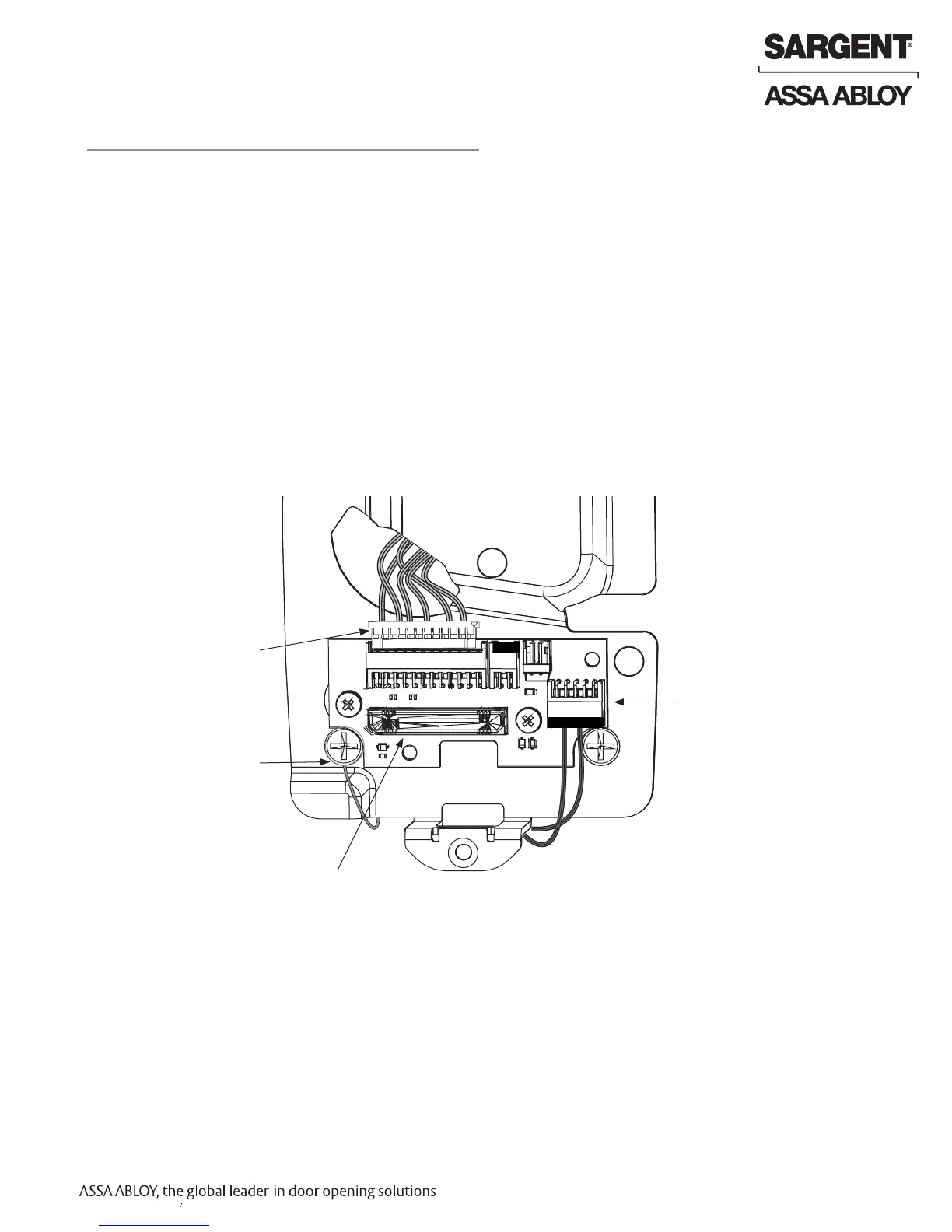
10 Installation of Connectors
1. Tuck excess cable into wire hole on inside of door.
2. Secure the mounting assembly while ensuring proper alignment of outside reader and fully tighten the
(2) through-bolts on the inside of the door to secure the reader and plate to the door.
Secure the following connectors to their respective terminals (Fig. 10):
A. Secure the 10-pin lock body assembly connector.
CAUTION - Do not touch or allow debris to enter connector contacts.
Secure Mounting Plate
IMPORTANT: Do not run wires through bottom hole in plate (Fig. 10) - it will damage wires and the controller connector.
Route wires around flange, do not route wires through the flange hole (Fig. 10).
B. Secure the 24-pin card reader connector (Fig. 10).
A
Lock Body (10-pin)
Board-to-Board
Connector
Ground
Lugs
Reader
(24-pin)
 Loading...