Do you have a question about the Assa Abloy RIXSON 91DCP and is the answer not in the manual?
Determine hand, verify frame squareness, check gaps, and confirm cut-out dimensions using templates.
Install closer in prepped frame using four 1/4-20 x 5/8" mounting screws. Ensure flush mounting.
Attach cover plate to closer mounting plate using six 6-32 x FHPMS screws.
Connect arm to closer spindle using 5/32" hex wrench and 1/4-20 x 3/4" screw.
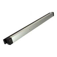
Slide track components into track, ensuring correct placement of stop block and slider.
Mount track assembly to door using specified screws, with or without optional spacer.
Tighten valves, position arm at 45°, and connect arm square to slider square.
Use 1/8" hex wrench to adjust backcheck, sweep, and latch speed valves for door control.
Adjust closing force using 3/8" hex wrench as needed, referring to the provided chart.
Adjust hold open function by manipulating the locking tab, set screws, and adjustment screw.
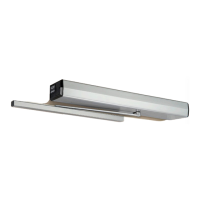
The Rixson Model 91DCP is an overhead concealed closer designed for metal frame installations, available in both non-hold open and hold open configurations. This device is suitable for doors hung with 4-1/2" x 4-1/2" butt hinges or 3/4" offset pivots; for other hanging means, factory consultation is required. The closer is designed to provide controlled door closing and, optionally, to hold the door open at a desired position.
The 91DCP closer operates by controlling the speed at which a door closes, preventing slamming and ensuring smooth operation. It features adjustable sweep, latch, and backcheck speeds, allowing for customization based on specific door and environmental requirements. The closing force is also adjustable, enabling the closer to accommodate various door sizes, weights, and positive room pressures. The optional hold open feature allows the door to be held open at a set position, which can be disengaged by pulling the door in the closing direction. This hold open feature is not permitted for use on fire-rated doors.
| Brand | Assa Abloy |
|---|---|
| Model | RIXSON 91DCP |
| Category | Door Opening System |
| Language | English |