EasyManua.ls Logo

Assa Abloy Corbin Russwin ED5000 Series User Manual

Assa Abloy Corbin Russwin ED5000 Series
28 pages
To Next Page IconTo Next Page
Page #1 background imageLoading...
Page #1 background image
FM209 10/20
Installation Instructions
Copyright © 2006, 2010, 2018, 2020 ASSA ABLOY Access and Egress Hardware Group, Inc. All rights reserved. Reproduction in whole or
in part without the express written permission of ASSA ABLOY Access and Egress Hardware Group, Inc. is prohibited.
For installation assistance contact Corbin Russwin
1-800-543-3658 • techsupport.corbinrusswin@assaabloy.com
Available on the following devices:
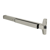
Rim
Mortise
SecureBolt
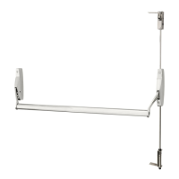
Concealed Vertical Rod
*Surface Vertical Rod
*Rod Guards Required (made by other manufacturers)
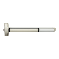
ED4000, ED5000 Series Exit Device
Delayed Egress
WARNING
This product can expose you to lead
which is known to the state of California
to cause cancer and birth defects or other
reproductive harm. For more information
go to www.P65warnings.ca.gov.

Questions and Answers:

Assa Abloy Corbin Russwin ED5000 Series Specifications

General IconGeneral
BrandAssa Abloy
ModelCorbin Russwin ED5000 Series
CategoryDoor Opening System
LanguageEnglish

Summary

Panic and Fire Rated Devices

Electrical Specifications

Details on input voltage, wire size, power consumption, and electrical requirements for the device.

DIP Switch Settings

Wiring Layout: Input/Output Wiring Descriptions

ElectroLynx Connector System for All Electrical Installation

ElectroLynx Wiring Options Overview with QC8 Hinge

ElectroLynx Wiring Options Overview with QC12 Hinge

ElectroLynx Wiring Deed with M93 Trim Monitor Option and QC12 Hinge

ElectroLynx Wiring Deed with Electrified Trim (ET) Option and QC12 Hinge

ElectroLynx Wiring Deed with M91 Latchbolt Monitor Option and QC12 Hinge

Wiring Diagram - Single Door Exit Only

Wiring Diagram - Single Door With Remote Inputs & Monitoring Outputs

Wiring Diagram - M93 Trim Monitor Entry with External Door Position Switch

Wiring Diagram - 9903 Electric Trim Control

Wiring Diagram - 9905 Electric Trim Control

Operating Instructions

Delayed Egress Mode

Describes the initial power-up sequence and armed state for delayed egress operation.

Troubleshooting

Related product manuals