7
Delayed Egress
Installation Instructions
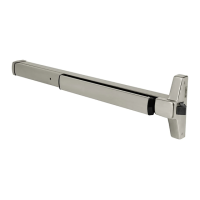
ED4000, ED5000 Series Exit Device
FM209 10/20
Copyright © 2006, 2010, 2018, 2020 ASSA ABLOY Access and Egress Hardware Group, Inc. All rights reserved. Reproduction in whole or
in part without the express written permission of ASSA ABLOY Access and Egress Hardware Group, Inc. is prohibited.
For installation assistance contact Corbin Russwin
1-800-543-3658 • techsupport.corbinrusswin@assaabloy.com
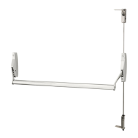
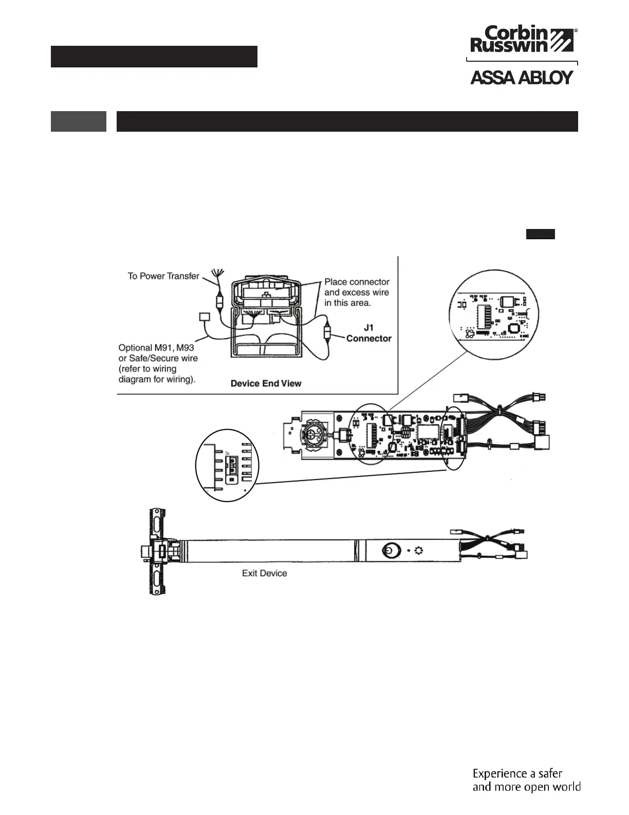
4 Installation of End Cover Assembly to Device
1. Turn end cover assembly over to circuit board side.
2. Ensure eight S2 Dip Switches are set for application (see previous page).
3. Slide end cover assembly into device, making sure not to pinch or crimp wires.
4. Connect device lock assembly harness to connector J1. Place wire connectors and excess wire
between end cover and P.C. board. (Figure 3, Device End View)
5. Check all connections before proceeding.
6. Proceed to device mounting (see packed instructions).
Figure 3
See DIP Switch settings on previous page
Connector J2
To power transfer
Connector J1
Plugs into device
Circuit Board
To Power Transfer
Device Assembly Harness
J5 detail view
NO C NC for 2-pin jumper selection. NO is default position.
NOTE: Review J5 Alarm Relay NO or NC selection above. If NC contact is required, remove PBCA/cover
assembly from rail, move 2-pin jumper to NC, then re-install PCBA/cover on rail.
 Loading...