5
Delayed Egress
Installation Instructions
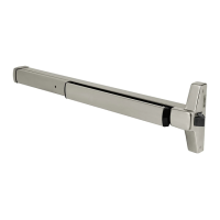
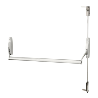
ED4000, ED5000 Series Exit Device
FM209 10/20
Copyright © 2006, 2010, 2018, 2020 ASSA ABLOY Access and Egress Hardware Group, Inc. All rights reserved. Reproduction in whole or
in part without the express written permission of ASSA ABLOY Access and Egress Hardware Group, Inc. is prohibited.
For installation assistance contact Corbin Russwin
1-800-543-3658 • techsupport.corbinrusswin@assaabloy.com
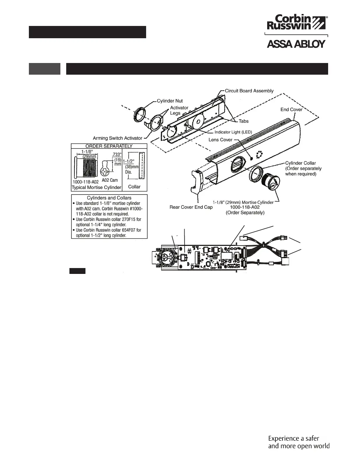
2 End Cover and P.C. Board Assembly
NOTES:
• Factory keyed orders will be shipped assembled.
• Prior to end cover assembly, device must be
cut to proper length to prevent damage to
circuit board. 36" Device cannot be field cut. A
maximum of 6" can be cut from a 48" device.
1. Slide circuit board assembly into end cover.
Front of assembly must be pulled away from
cover to prevent damage to LED indicator
light. Housing assembly is in correct position
when LED can be inserted in lens cover on
end cover. (Figure 2)
2. Insert cylinder (mortise and collar) into end
cover with keyway horizontal and toward
closest end of end cover.
Activator Legs
Arming Switch Activator
Circuit Board
Label
To Power Transfer
To Device Connection
To Device Connection
Circuit Boar
o Device
Figure 2
3. Slide arming switch activator over cylinder
so activator legs are on each side of switch.
4. Secure parts in place with cylinder nut. Be
certain flange on cylinder nut inserts into
arming switch activator to allow rotation of
activator.
5. Verify assembly by rotating key counter-
clockwise and clockwise. Key should move
freely and arming switch should trip for
both rotation directions. If key does not
rotate freely, verify cylinder nut is in correct
orientation. If arming switch does not trip,
activator legs on arming switch activator
can be bent to reduce or increase rotational
travel.
 Loading...