17
Delayed Egress
Installation Instructions
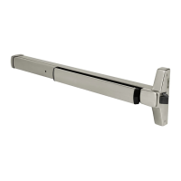
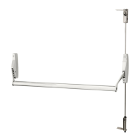
ED4000, ED5000 Series Exit Device
FM209 10/20
Copyright © 2006, 2010, 2018, 2020 ASSA ABLOY Access and Egress Hardware Group, Inc. All rights reserved. Reproduction in whole or
in part without the express written permission of ASSA ABLOY Access and Egress Hardware Group, Inc. is prohibited.
For installation assistance contact Corbin Russwin
1-800-543-3658 • techsupport.corbinrusswin@assaabloy.com
Vertical
Reference
Horizontal
Reference
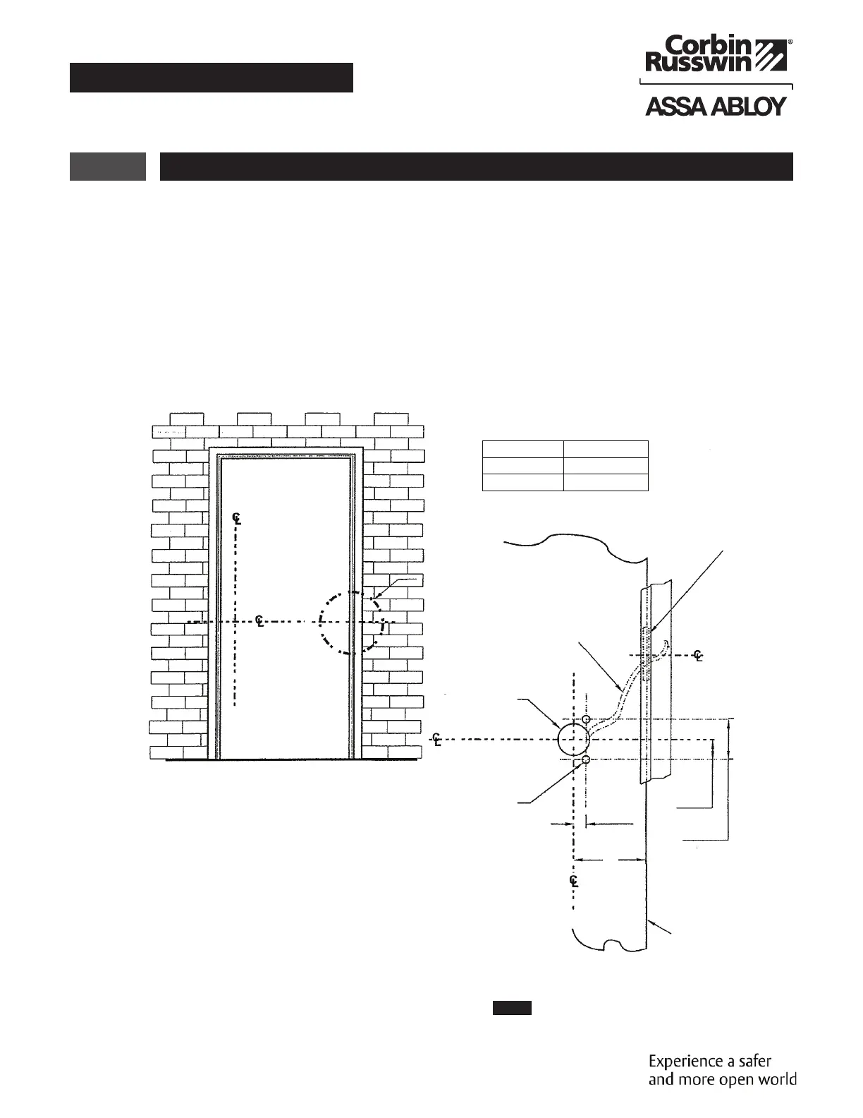
Hinge Edge Detail
INSIDE FACE OF DOOR
Clear Channel Access
Required for Wire
Connection
Hinge
1" (25mm) Dia.
(Wiring Access)
Horizontal Reference
Device Centerline
(See Note 5)
Exit Device End Clamp Mounting
Holes (For reference only)
HINGE EDGE DETAIL
Hinge Edge
Of Door
5/16" Ref
(8mm)
5/8" Ref
(16mm)
A
1-1/4" Ref
(32mm)
Exit Device
ED4000 Series
ED5000 Series
Dim. A
1-11/16" (43mm)
2-5/16" (59mm)
Conducting Hinge or
Approved Power Transfer
(made by other manufacturers)
14 Non-ElectroLynx Door Prep
Figure 8
Refer to Figure 8 for non-ElectroLynx Door preparation.
NOTE:
• Do not scale drawing.
• Dimensions are in inches (") and millimeters (mm).
• LHR H.M. opening shown. Details are typical for all opening materials (both hands).
• This preparation is an addition to preparation shown on device template.
• See device template to locate centerline.
• Shields for wiring access recommended for insulated and composite doors.
• Locate and prepare wiring access holes when installing device.
 Loading...