13
Fig. 35
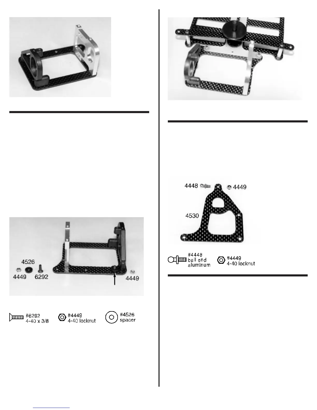
❑ Figs. 36 & 37 In the same bag you will find three
#4526 plastic T-bar spacers and three #6292 4-40 x 3/8”
FHSScrews, and three #4449 4-40 small aluminum locknuts.
For the standard assembly we will only need two of each. Install
two #6292 screws in the two outer T-bar mounting holes of the
lower pod, as shown. Place one of the #4526 plastic T-bar
spacers over each screw. Line the screws up with the two outer
mounting holes on the back of the T-bar. Now slide the T-bar
over the screws and secure the assembly with the two #4449
4-40 small aluminum locknuts.
Racer’s Tip: You can stiffen the
front to rear flex of the T-bar for different conditions. Install the
third #4526 T-bar spacer, #6292 4-40 screw and #4449 4-40
small aluminum locknut into the center hole of the T-bar
mounting holes.
We will discuss this in more detail in the tuning
section at the end of the manual.
Fig. 36
Fig. 37
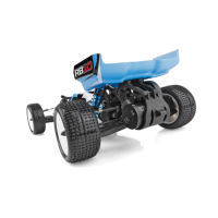
❑ Fig. 38 Now remove the #4530 graphite upper damp-
ener plate, one #4448 aluminum ball end, and one #4449 4-40
small aluminum locknut. Layout the dampener plate as shown.
Now install the #4448 aluminum ball end into the front hole and
thread the #4449 4-40 small aluminum locknut onto the threaded
end. Make sure the ball end is up and the cutaway side is to the
left as shown.
Fig. 38
❑ Figs. 39 & 40 Take out two #6919 4-40 x 5/16”
BHSScrews, and one #6917 4-40 x 3/8” BHSScrew. Place the
#4530 dampener plate assembly on top of the rear pod assem-
bly. The cut away side of the dampener plate will be to the left
or drivers side and the plastic dampener post will be coming
through the dampener hole as shown. Use the #6917 screw to
secure the dampener plate to the left molded bulkhead and the
two #6919 screws to the right side aluminum motor plate as
shown.