1. Basic information
PHG 300A / 301A User Manual Page 4 of 40
5.1.1 Interferential and AMF currents ..................................................................................................................... 34
5.1.2 Kotz’ current – Russian stimulation ................................................................................................................ 34
5.1.3 TENS and SP-TENS current ............................................................................................................................. 34
5.1.4 Diadynamic currents ...................................................................................................................................... 35
5.1.5 Ultra Reiz current ........................................................................................................................................... 35
5.1.6 Rectangular impulses ..................................................................................................................................... 35
5.1.7 Triangular impulses ........................................................................................................................................ 36
5.1.8 Tonolysis......................................................................................................................................................... 36
5.1.9 Microcurrents ................................................................................................................................................. 36
5.1.10 USS – Unipolar Sine Surge .............................................................................................................................. 36
5.1.11 Galvanic current ............................................................................................................................................. 37
5.1.12 Ultrasound therapy ........................................................................................................................................ 37
5.1.13 Combined therapy .......................................................................................................................................... 37
5.2 CONTRAINDICATIONS FOR ULTRASOUND THERAPY .................................................................................................................. 37
5.3 CONTRAINDICATIONS FOR ELECTROTHERAPY ......................................................................................................................... 38
5.4 CONTRAINDICATIONS FOR COMBINED THERAPY ..................................................................................................................... 38
6. ACCESSORIES ......................................................................................................................................................... 39
6.1 STANDARD ACCESSORIES .................................................................................................................................................. 39
6.2 OPTIONAL ACCESSORIES ................................................................................................................................................... 39
Table of figures
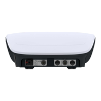
Figure 3.1. Electrotherapy sockets ............................................................................................................................................. 8
Figure 3.2. Connection of electrodes ......................................................................................................................................... 9
Figure 3.3. Ultrasound head sockets .......................................................................................................................................... 9
Figure 3.4. Output circuits for combined therapy .................................................................................................................... 10
Figure 3.5. Patient’s stop switch socket ................................................................................................................................... 10
Figure 3.6. Screen view – date and time edition ...................................................................................................................... 11
Figure 4.1. Field description ..................................................................................................................................................... 18
Figure 4.2. A sample view of therapy selection in channel 2 ................................................................................................... 19
Figure 4.3. Location of channel selection tabs ......................................................................................................................... 20
Figure 4.4. Screenshot sample view for dual circuit electrotherapy A+B ................................................................................. 22
Figure 4.5. Screenshot sample view for single circuit electrotherapy A and B ......................................................................... 22
Figure 4.6. Screenshot sample view for electrotherapy sequences ......................................................................................... 23
Figure 4.7. Screenshot sample view for combined therapy ..................................................................................................... 23
Figure 4.8. Screenshot sample view for ultrasound therapy .................................................................................................... 24
Figure 4.9. Information screen sample view ............................................................................................................................ 25