WARNING: During system warm-up and when
adjusting system hoses or valving heads, each HAT
switch must be in the Off (center) position to
prevent accidental head firing.
[6] Head Activate/Deactivate Test (HAT) Switch
(user-added option only)
The head activate/deactivate test switch (HAT) controls the
valving signals to the automatic heads. The HAT switch is located
on the melt unit's front panel, and can be identified by the three
positions on the switch body: Off to disable the head control
circuit; TEST allows the heads to be test fired independently; and
RUN enables the head control circuit and allows head valving
signals from timers, drivers, limit switches, or photoeyes to actuate
the heads.
KB30, KB50 and KB100 melt units can have a maximum of three
HAT switches to control up to three independent valving head
signals. The HAT switches can be connected in a variety of
combinations since each melt unit can support up to six automatic
heads.
!
2000334
HEATING
OVERTEMP
REFER TO
SERVICE MANUAL
WHEN LIT
ON
OFF
PUMP
ON
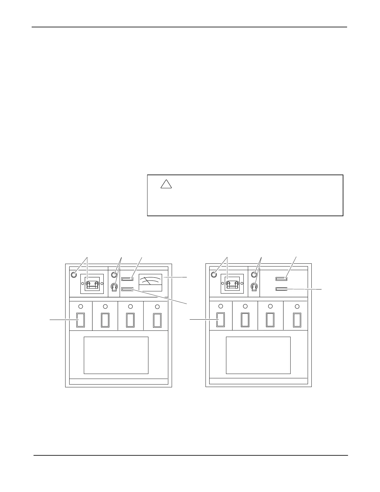
POWER TANK TEMPERATURE
APPLICATOR
1
4
2
5
6
HEATING
OVERTEMP
REFER TO
SERVICE MANUAL
WHEN LIT
ON
OFF
PUMP
ON
POWER TANK TEMPERATURE
APPLICATOR
1
4
3
2
5
6
Bimetallic Temperature Control
Solid-State Temperature Control
© Copyright Astro Packaging 2009 KB30, KB50 and KB100 Series Hot Melt Units 19600-159 Rev. A 04/09/09 19
 Loading...