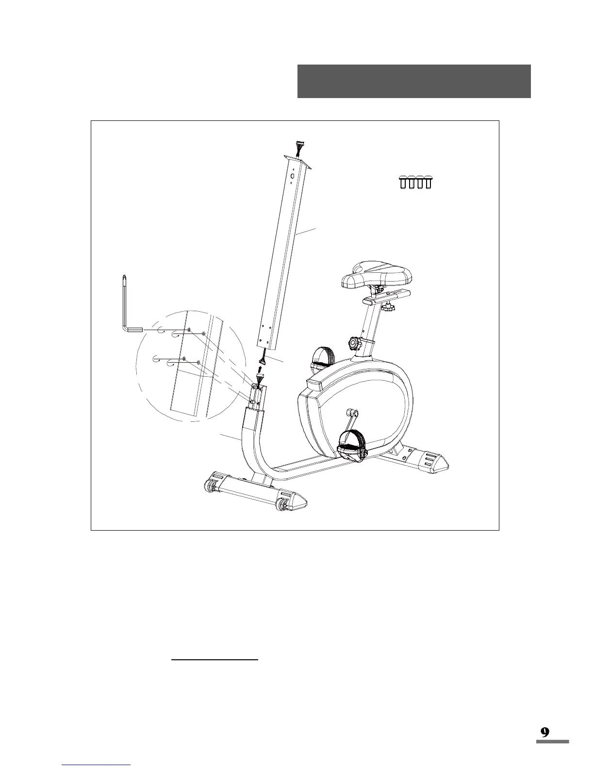
Connect the Computer Middle Wire (No. I2) from the Post Tube (No. I) to the wire
from the Main Frame (No. S) then attach Post Tube (No. I) to the Main Frame (No.
S) connecting piece. Ensure that the screw holes of the Post Tube (No. I) are faced
outward. To secure the Post Tube (No. I) to the Main Frame (No. S), insert the Allen
Wrench (No. L4) through each hole of the Post Tube (No. I) and turn the Allen
Bolts (No. S15) counter-clockwise, as shown in the diagram above.
NOTE: Allen Bolts (S15) should not be visible after this installation.