3
NT2508 / NT2504 / NT1308 / NT1304 / NT4004
English
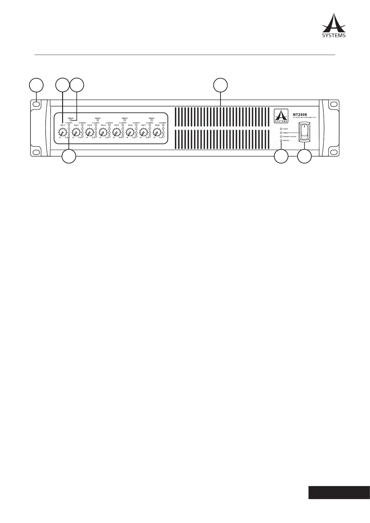
1. Mounting Holes
These holes are for mounting the NT series network
amplier in a standard 19” rack.
2. Output Level Control Knobs
Every output channel is equipped with a rotary knob
for adjusting the nal output level. These controls can
be deactivated using POLE 6 on the rear-panel DIP
switch�
3. IN LEDs
Every input channel is equipped with a 4-segment IN
LED level meter, including a CLIP/PROTECT indicator.
4. BRIDGE LED
This LED lights when the two corresponding channels
are bridged with one another.
NOTE: Every input channel is equipped with one output level
control knob, one IN LED and 1 level meter� Each channel pair
features a BRIDGE LED�
5. Cooling Inlet Vents
Cool air is drawn in here� Please do not cover these
vents for any reason as you risk overheating the NT�
6. Indicators
POWER: Lights when the device is on�
DISABLE: Lights when the power switch is disabled.
STANDBY/UNLOCK: Lights when the NT system is in
the Standby mode.
PROTECT: Lights when the protect circuity is active�
7. Power Switch
Flick this switch to turn the unit on and enter it into
STANDBY mode. Please note that this switch can be
disabled through the onboard software. If the power
switch becomes unresponsive, check your power
settings�
WARNING: The NT requires up to 2 minutes to be fully discharged
after the power is turned o. During this time the system cannot
be powered on properly.
3. CONTROLS AND I/O
FRONT PANEL
2
1
3
4
5
76