4
NT2508 / NT2504 / NT1308 / NT1304 / NT4004
English
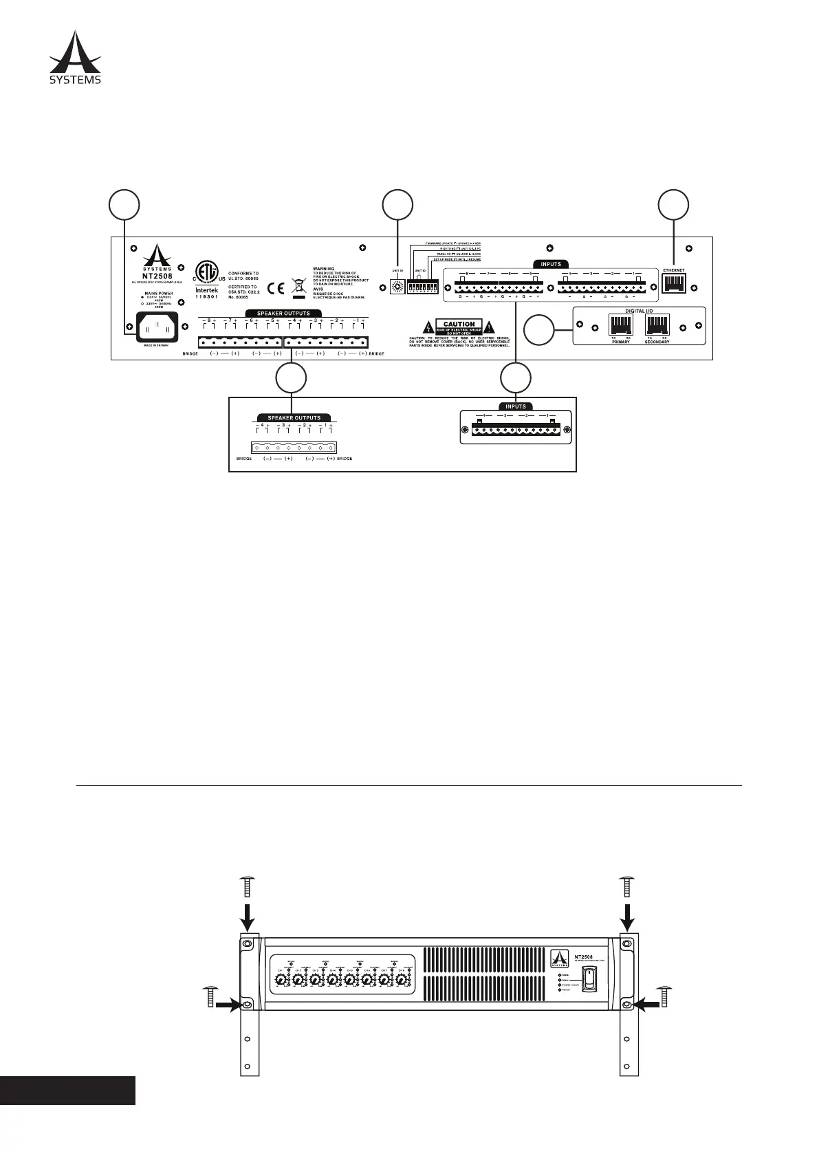
REAR PANEL
1. AC Power Connector
This power inlet is for connecting a standard IEC
power cable. Under no circumstances should the user
remove the grounding pin on the power cable.
2. Unit ID Controls
The Unit ID controls consist of a single rotary switch
as well as 8-pin DIP switch. These essentially adjust
various controls and settings as well as things like
rmware updates. More information on Unit ID settings
can be found in the relevant area of this manual. These
controls extend to IP address settings and initialization.
3. INPUT Connectors
Line-level Euroblock input connectors are oered.
The Asystems NT2508, NT2504, NT1308, NT1304 and NT4004 share the same basic I/O design and layout. The major
dierence is that the NT2508 and NT1308 have 8 line input channels and 8 speaker output channels, while the NT2504,
NT1304 and NT4004 all have 4 input connectors and 4 speaker output channels (as shown below).
NT2508, NT1308, NT2504, NT1304 and NT4004 are compatible with standard 19” audio equipment racks. Slide the NT
in to the rack and secure it with four Phillips screws and appropriate square nuts. The NT network ampliers each take
up 2 standard units of rack space�
4. INSTALLATION AND SETUP
4.1 RACK MOUNTING
6
2 5
4
1
3
++++
G
NT2504 / NT1304 / NT4004
NT25408 / NT1308
4. SPEAKER OUTPUTS (Amplied Output)
For connecting passive loudspeakers�
5. ETHERNET Connector
RJ-45 connector for connecting the NT series network
amplier to a PC or local area network.
6. DIGITAL I/O
This slot is for Asystems’ DT44 or DT88 Dante
Networking card to enable the NT as a networking
portal to other Dante-enabled devices. The Dante
Networking card is sold separately�