9
NT2508 / NT2504 / NT1308 / NT1304 / NT4004
English
5. CONTROL SOFTWARE
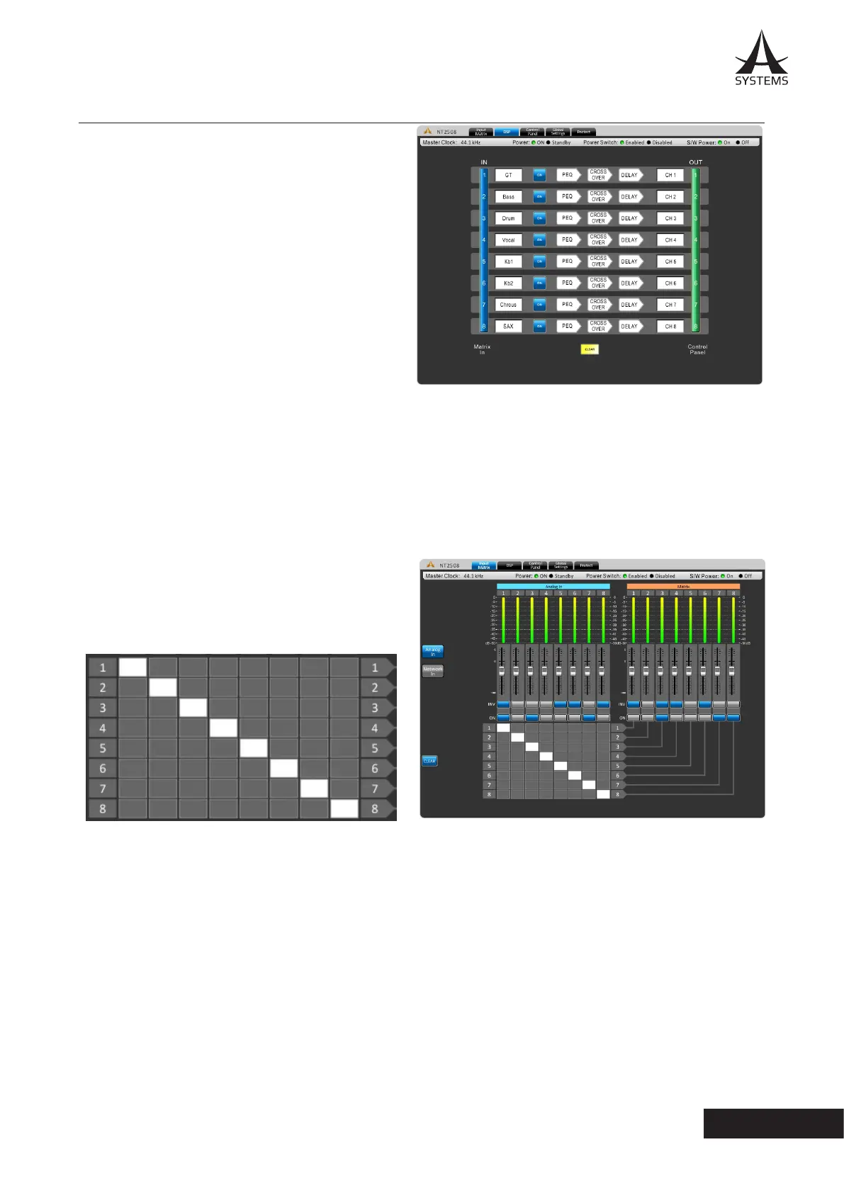
DSP
The DSP page will give you an overall prole of input and
output mixes as well as signal processors.
Name Cell: The white boxes at the left and right of
each row will display the name of each input and output
channel. Users can edit the name for each channel by
double-clicking on the white box.
ON/OFF: This button will allow the user to switch the
corresponding input channel on and o.
Signal Processor Cells: Every input/output channel has
a row of three arrow shaped cells� The signal processors
included are the PEQ, crossover and delay. These signal
processors are set by default but can be bypassed by the
user�
Channel In: Clicking the blue bar to the left of the screen will jump directly to the “Channel In Matrix” tab.
Channel Out: Clicking this green bar allows the user direct acccess to the “Control Panel” tab.
Clear: Clicking this button resets all DSP congurations.
Analog In Matrix
In this page, you can assign any input source to any output
channel by clicking the corresponding cell in the cell matrix.
Example:
The image below shows how to assign input channels 1
through 8 to their corresponding outputs�
Analog In and Network In: Use these two buttons to view analog input sources connected via rear panel, as well as
digital input sources from the Dante card�
INV: Select this button to invert the phase of the corresponding channel.
ON: Select this button to turn the corresponding signal on and o.
CLEAR: Clicking this button erases all assigned input/output routing.