131
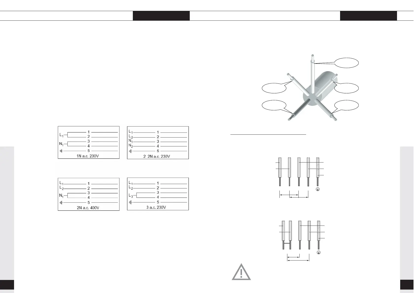
A view of the power cable is shown schematic below:
2 phase connection
2 positive + 2 negative 2 2N a.c. 230 V
The fuse box in your home must be fitted with a 16 A fuse.
2 fase + 1 nul 2 2N a.c. 400 V
The fuse box in your home must be fitted with a 16 A fuse.
Do not connect the 3rd phase.
INSTALLATION electrical connection
negative connection N
(blue and brown)
positive connection L1
(grey)
positive connection L2
(black)
130
INSTALLATION
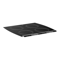
The model number, power supply and connected load are specified on
the data plate.
The data plate is attached to the base of the appliance.
The connection cable is of the type Y.
This means that the connection cable may only be replaced by the
manufacturer, the service organisation or similarly qualified persons, in
order to prevent dangerous situations.
Refer to the figure below for the wiring diagram, which can also be
found on the underside of the appliance.
If you want to make a fixed connection, make sure that a multi-polar
switch with a contact separation of at least 3 mm is fitted in the supply
line.
electrical connection
 Loading...