EasyManuals Logo

Atari 400 Hardware Manual

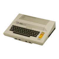
Atari 400
113 pages
To Next Page IconTo Next Page
To Previous Page IconTo Previous Page
Page #35 background imageLoading...
Page #35 background image
INTERRUPT
SUMMARY
I
I I
STATUS
I
I
NAME
FUNCTIONS
I
ENABLE
I
STATUS
RESET
I
I I I
I
I
Display
I
NMIEN
I
NMIST
Address
I
I
NMI
Instruction
I
(Bits
6
thru
7)
I
(Bits
5
thru
7)
NMIRES
I
I
INTERRUPTS
Vert.
Blank
I
Normally
Zero
Nol.:'mally
Zero
(R ~
sets
all
NMI
I
I
Reset
Button
I
~Disabled)
~no
interruEt)
status
together)
I
I I
I
I
KEYS
I
IRQ
EN
IRQST
Reset
(to
true)
I
I
Serial
I
(Bits
0
thru
7)
(Bits
0
thru
7)
By
Zero
in
I
I
Eorts
I
zero
is
Normally
True
Corresponding
I
I
Timers
I
(Disabled)*
(no
interrupt)
Bit
of
IRQEN
I
I
I
~exceEt
Bit
3)*1
I
IRQ
I
I
INTERRUPTS
Peripheral
I
DO
of
PACTL
D7
of
PACTL
Reset
by
.
I
A
!Normally
Zero
!Normally
Zero
Reading
PORT
I
I
~Disabled)
l{no
interruEt)
Register
I
I I
I
Peripheral
I
DO
of
PBCTL
I
D7
of
PBCTL
Reset
by
I
B
!Normally
Zero
!Normally
Zero
Reading
PORT
I
I
{Disabled)
I {no
interruEt)
Register
E.
CONTROLLERS
A
variety
of
controllers
can
be
plugged
into
the
four
jacks
on
the
front
of
the
console.
This
includes
joysticks,
paddle
(pot),
twelve-key
keyboard,
and
light
pen (when
available).
A
B
The
controller
ports
are
read
through
the
PORTA
and
PORTB
regisers
and
the
POT
and
TRIG
registers.
The
OS
reads
these
registers
during
vertical
blank
and
stores
into
its
own
RAM
locations.
These
are
STICK,
PADDLO
through
PADDL7,
PTRIG'S and STRIG'S. The
OS
sets
up
PORTA
AND
PORTB
for
input.
This
is
done
by
setting
PACTL
or
PORTB
(Port
Control)
bit
2
to
a 0
(to
select
the
dire~tion
control
register),
then
writing
all
O's
to
the
desired
port.
PACTL
(PBCTL)
bit
2
is
then
changed
back
to
a
1,
allowing
the
program
to
read
from
the
port.
The
ports
can
also
be
I
I
I
I
I
I
I
I
set
up
for
output
by
writing
1's
instead
of
O's
while
the
direction
control
mode
is
selected.
Joysticks:
The
joysticks
have
four
switches,
one
each
for
right
(R),
left
(L),
back
(B) and
forward
(F).
These
switches
are
read
through
PORTA
and
PORTB.
A
fifth
switch
is
activated
by
pressing
the
red
trigger
button.
The
trigger
buttons
are
read
from
TRIGO
through
TRIG3. A
value
of
0
indicates
that
a
button
has
been
pressed
and a 1
indicates
that
it
has
not
been
pressed.
II.
30

Other manuals for Atari 400

Questions and Answers:

Question and Answer IconNeed help?

Do you have a question about the Atari 400 and is the answer not in the manual?

Atari 400 Specifications

General IconGeneral
ManufacturerAtari
Model400
TypeHome Computer
Release Year1979
CPUMOS Technology 6502
CPU Speed1.79 MHz
ROM10 KB
Operating SystemAtari OS
KeyboardMembrane keyboard
RAM8 KB (expandable to 48 KB)
GraphicsANTIC and GTIA chips
Sound4 channels
DisplayRF output for connection to TV
StorageOptional cassette tape drive or floppy disk drive
PortsCartridge
Display Resolution320x192 (16 colors)

Related product manuals