EasyManuals Logo

Atari 400 Hardware Manual

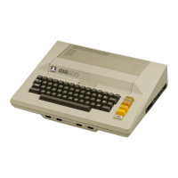
Atari 400
113 pages
To Next Page IconTo Next Page
To Previous Page IconTo Previous Page
Page #95 background imageLoading...
Page #95 background image
Mixing
Graph
ic
s
~odes,
c ~
nt.
II.
PROCEDURE
TO
SET
UP
SCRE
:::N
H :
HXED
MODES,
cont.:
5.
Convert
all
bytes
to
decimal.
example:
Bvte
(HEX)
DEC
LMS
46
70
Mode
1
06
6
Mode
7
OD
13
Mode
2
07
7
6.
Execute
a
graphics
mode
(+16).
call
on
the
computer
using
the
max
RAM
example:
GRAPHICS
7 +
16
7.
PEEK
the
Display
List
pointer
and
use
it
to
calculate
a
variable
labelled
"START".
example:
START
PEEK(560)
+
PEEK(561)
*
256
+ 4
8.
If
the
max
RAM
mode
is
at
the
top
of
the
screen,
then
skip
this
step:
Poke
the
LMS
byte
to
location
START-1.
example:
POKE
START-1,70
9.
Every
mode
line
requires
a
mode
byte
in
the
Display
List
in
the
same
order
as
the
mode
line
E
&ppear
on
the
screen.
The
mode
bytes
must
be
POKED
into
the
Display
List
at
location
START +
offset,
where
offset
mode
line
#.
Example:
MODE
LINE
# POKE
INSTRUCTION
2
POKE
START +
2'
6
3
POKE START +
3'
6
MODE
1 4 POKE START
+
4,6
5
POKE
START +
5,6
6 POKE START +
6'
6
MODE
7
see
note
for
mode
7
(max
RAM
mode)
MODE
2
63
POKE START +
6
3'
7
64
POKE START
+
64,7
NOTE:
_
The
Display
List
will
alre
a
dy
be
correct
for
the
max
RAM
mode,
'
therefore
its
mode
bytes
do
not
need
to
be
POKEd.
B
-4-

Other manuals for Atari 400

Questions and Answers:

Question and Answer IconNeed help?

Do you have a question about the Atari 400 and is the answer not in the manual?

Atari 400 Specifications

General IconGeneral
ManufacturerAtari
Model400
TypeHome Computer
Release Year1979
CPUMOS Technology 6502
CPU Speed1.79 MHz
ROM10 KB
Operating SystemAtari OS
KeyboardMembrane keyboard
RAM8 KB (expandable to 48 KB)
GraphicsANTIC and GTIA chips
Sound4 channels
DisplayRF output for connection to TV
StorageOptional cassette tape drive or floppy disk drive
PortsCartridge
Display Resolution320x192 (16 colors)

Related product manuals