CS1642A / CS1644A User Manual
10
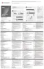
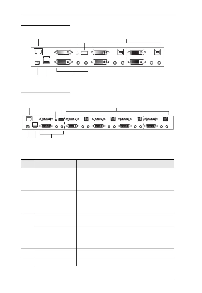
CS1642A Rear View
CS1644A Rear View
No. Component Description
1 DCC Port
(Daisy Chain
Control)
This RJ-45 port is used to connect two CS1642
A /
CS1644
A units together when setting up DCC mode
for a quad view display. See Quad-View (DCC
Mode), page 16 for instructions.
2 DCC Switch This switch is used to specify the Host and Client
when setting up two CS1642
A / CS1644A units in
Quad-View DCC mode. See Quad-View (DCC
Mode), page 16.
3 USB 2.0 Peripheral
Port
USB 2.0 peripherals (printers, scanners, etc.) can
plug into this port.
4 KVM Port Section The cables that link the switch to your computers
plug in here. Each KVM port section is comprised of
a microphone jack, speaker jack, USB type B socket
and two DVI-I connectors
5 Power Jack The power adapter cable plugs into this jack.
6 USB Console Ports Your USB keyboard and USB mouse plug in here.
4
3
1
5
6
7
2
 Loading...