Manual, Control Module, PROFINET, DL10
Document #9620-20-C-DL10-04
Pinnacle Park • 1031 Goodworth Drive • Apex, NC 27539 • Tel: 919.772.0115 • Fax: 919.772.8259 • www.ati-ia.com
C-14
2.2.1 Arc Prevention Circuit Behavior during Coupling
The Master module incorporates ATI’s Arc Prevention Circuit, which extends the life of all
electrical power contacts by eliminating arcing caused by inductive loads and high inrush current
during coupling/uncoupling. The Arc Prevention Circuit makes it possible for the customer to
couple/uncouple without switching power off and prevents damage to the contacts.
In the Master module, the Arc Prevention Circuit controls the ON/OFF status of the following (2)
power supplies:
2. Input and Logic power US1+
3. Output power US2+
The behavior of the Arc Prevention circuit is more fully described in the following sections.
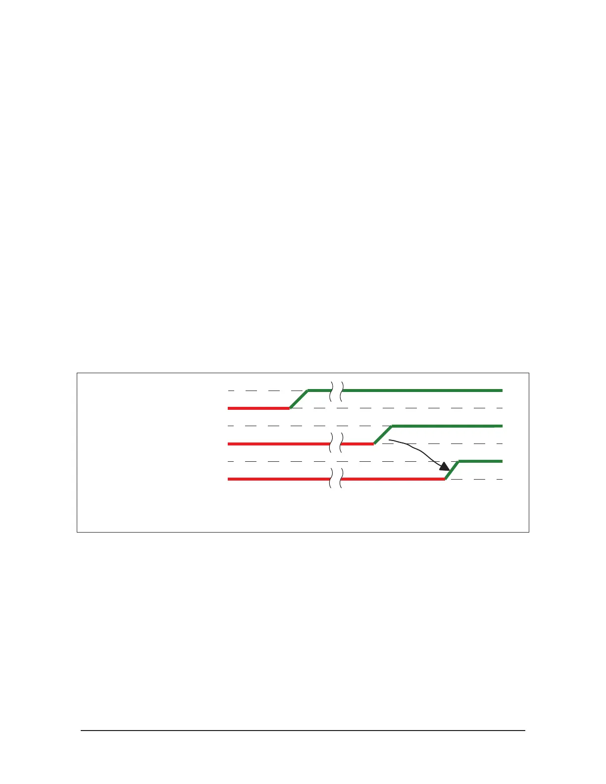
2.2.2 Arc Prevention Circuit Behavior during Coupling
The behavior of the Arc Prevention circuit during coupling can be more clearly understood by
referring to Figure 2.3.
When the robot and Master approach the Tool for pick up, electrical contact between the Master
and Tool pin contacts occurs. Soon after the Latch command is turned ON, the Arc Prevention
Circuit will turn on US1 and US2 power. The time delay between when the LATCH output is
turned ON to when power is actually available to the EOAT (time T
1 in the diagram) is less than
100 ms.
Important: The Arc Prevention Circuit will only allow power to pass to the Tool after the LATCH
command has been issued and the Master and Tool module’s electrical contacts are fully engaged.
Figure 2.3—Power On Timing
Profinet US1 and
US2 Power
Electrical Contact Between
Master and Tool
LATCH Output
ON
OFF
ON
OFF
ON
OFF
T1
T1 = Power Switch ON-delay (Less than 100 ms)