Manual, Control Module, PROFINET, DL10
Document #9620-20-C-DL10-04
Pinnacle Park • 1031 Goodworth Drive • Apex, NC 27539 • Tel: 919.772.0115 • Fax: 919.772.8259 • www.ati-ia.com
C-7
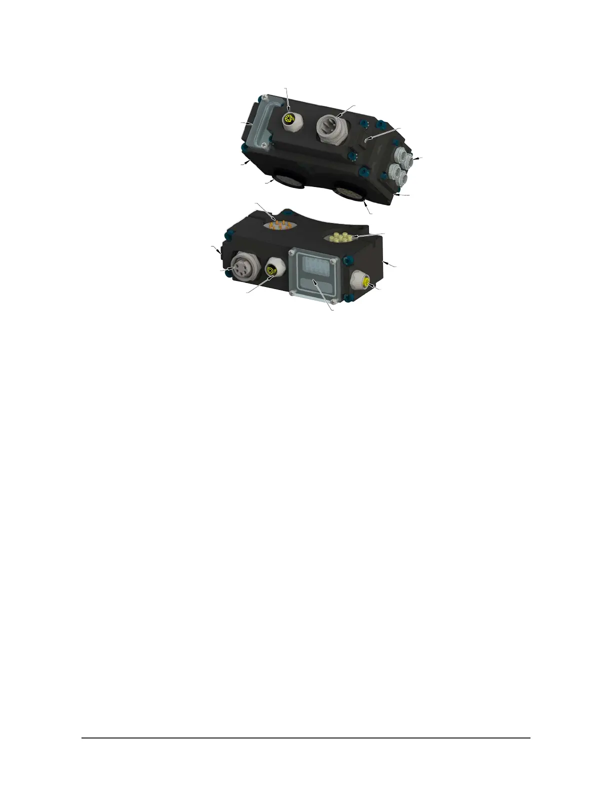
Figure 1.1—DL10 Modules
10-Pin Signal Contact
10-Pin Spring Signal Contact
and Rubber V-ring Seal
4-Pin Female M12 D-coded
PROFINET Connector
PROFINET Connector
4-Pin Female M12
TSI Connector
(4) 3-Pin Female M8
Sensor Connector
RTL, Lock, and Unlock
5-Pin Male
Auxilary Power Connector
M5x0.8 Threaded Hole
FE Ground Terminal Connection
5-Pin Female
Auxilary Power Connector
SF, Ethernet 2, BF,
Ethernet 1 LED's,
and Reset Switch
M5x0.8 Threaded Hole
FE Ground Terminal Connection
Valve Signal Pin Block
(not visible)
7-Pin Contact
7-Pin Spring Contact
and Rubber V-ring Seal
DL10 Master Module
DL10 Tool Module (Shown)
1.2 DL10 Tool Module
The module has the following connections:
• (1) 4‑pin female M12 D‑coded PROFINET connector.
• (1) 5‑pin male auxiliary power connector.
• (1) 4‑pin female M12 TSI connector.
• (1) M5 x 0.8 threaded hole for FE ground terminal connection that is accessed by removing the M5
set screw plug.
The TSI connector supports the use of a mechanical limit switch that has (2) sets of N.O. contacts
(double‑pole, single throw).
The Tool module employs a series of (5) push button switches for setting of the Tool‑ID input that allows
the customer to distinguish between the different tools that are used in a robotic cell or on a production
line. The Tool‑ID is reported through the Master module bitmap. PROFINET requires a FE ground, the
Tool module provides a M5 x 0.8 FE ground terminal that is passes FE ground to the customer tooling. See
Section 2.1.1—PROFINET Interface Information for PROFINET bitmap and detailed I/O information.
1.3 DL15 Tool Module
The module has the following connections:
• (1) 4‑pin female M12 D‑coded PROFINET connector.
• (1) 5‑pin male auxiliary power connector.
• (1) 4‑pin female M12 TSI connector.
• (1) M5 x 0.8 threaded hole for FE ground terminal connection that is accessed by removing the M5
set screw plug.
The TSI connector supports the use of a single (non‑series), PL e rated, RIFD based contactless safety
switches.
The Tool module employs a series of (5) push button switches for setting of the Tool‑ID input that allows the
customer to distinguish between the different tools that are being used in a robotic cell or on a production
line. The Tool‑ID is reported through the Master module bitmap. PROFINET requires a FE ground, the
Tool module provides a M5 x 0.8 FE ground terminal that is passes FE ground to the customer tooling. See
Section 2.1.1—PROFINET Interface Information for PROFINET bitmap and detailed I/O information.