Manual, Robotic Tool Changer Third Generation Teaching Aids
Document #9610-20-3370-02
Pinnacle Park • 1031 Goodworth Drive • Apex, NC 27539 USA • Tel: 919.772.0115 • Fax: 919.772.8259 • www.ati-ia.com • Email: info@ati-ia.com
16
8. Drawings
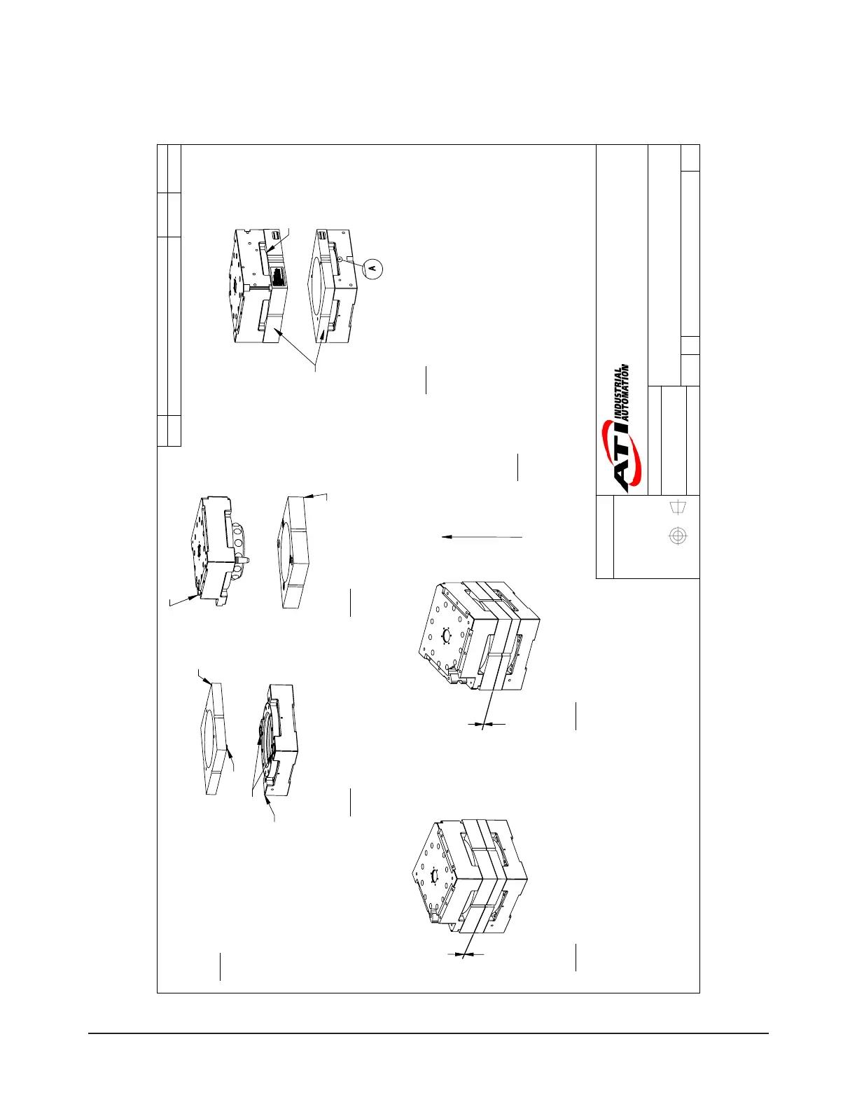
8.1 QC-210 Teaching Aid Assembly
3rd ANGLE PROJECTION
QC-210 Master Plate
Master Side Aid
These faces
must be
parallel
Locate Flat ID 'A'
on mating surface
of Master Plate
Tool Side Aid
QC-210 Tool Plate
Bushings
Locating Boss
1mm
1mm
+ Z Direction
Step 1:
Place the Tool Plate in the Tool
Stand. Programs should be written
with the Tool Plate resting
in the Tool Stand.
Step 2:
Mount the Tool Side Aid over the Tool
Plate by inserting the Locating Bosses into
the Bushings. Magnets will ensure the Tool
Side Aid will remain in place.
Step 3:
Mount the Master Side Aid to the QC Master Plate
ensuring that the taper pins enter the holes in the
Master Side Aid. Magnets will ensure the Master
Side Aid will remain in place.
Step 4:
Bring the Master Plate Assembly to a position directly
over the Tool Plate Assembly. The Master Plate
Assembly's face should be parallel to the Tool Plate
Assembly's face. Ensure that the orientation of the
Master and Tool assemblies are such that the Flat ID's
correspond (i.e. 'A' Master to 'A' Tool, etc.).
Step 5:
Move the Master Plate Assembly slowly downward until
the Master and Tool Side Aids are approximately 1mm
apart.
Step 6:
Adjust the position of the robot to
correct for any lateral misalignment.
Use the edges of the Teaching Aid to
align the Tool Side and Master Side.
Step 7:
Record the robot coordinates from Step 6. A correction must now be made to the
Axial Tool Coordinate to account for the thickness of the Tool and Master Side
Teaching Aids. Only in this way can the correct "Pick-up" and "Replacement"
coordinates be determined. Perform the following calculation to determine the "Pick-
up" and "Replacement" location:
Z "Pick-up" Coordinate = (+ Z Coordinate from Step 6) - (50mm)
Master and Tool
Flat ID's must match
Rev.
Description
Initiator
Date
01
Initial Drawing
DJB
8/31/2017
B
1:5
1 1
REVISION
NOTES: UNLESS OTHERWISE
SPECIFIED.
DO NOT SCALE DRAWING.
ALL DIMENSIONS ARE IN
MILLIMETERS.
DRAWN BY:
CHECKED BY:
D. Bohle 8/31/2017
M. Gala 9/18/2017
TITLE
SCALE
SIZE
DRAWING NUMBER
PROJECT #
SHEET OF
9230-20-8004
170828-3
01
PROPERTY OF ATI INDUSTRIAL AUTOMATION, INC. NOT TO BE REPRODUCED IN ANY
MANNER EXCEPT ON ORDER OR WITH PRIOR WRITTEN AUTHORIZATION OF ATI.
1031 Goodworth Drive, Apex, NC 27539, USA
Tel: +1.919.772.0115 Email: info@ati-ia.com
Fax: +1.919.772.8259 www.ati-ia.com
ISO 9001 Registered Company
QC-210 TEACH3 Instruction Drawing

 Loading...