Manual, Robotic Tool Changer Third Generation Teaching Aids
Document #9610-20-3370-02
Pinnacle Park • 1031 Goodworth Drive • Apex, NC 27539 USA • Tel: 919.772.0115 • Fax: 919.772.8259 • www.ati-ia.com • Email: info@ati-ia.com
9
3. Installing and Aligning (Tool Changer Set-up)
DANGER: The gap between the Master and Tool Side Teaching Aids is a pinch point.
Physical contact in these pinch points will result in serious or permanent injury to personnel.
All personnel should be prevented from placing any body part or clothing in the gap,
especially during actuation of the locking mechanism.
The following instructions apply to all Teaching Aids. Additionally, labels with abbreviated operating instructions
are on the Master side. On the ATI website, http://www.ati-ia.com/library/video_listing.aspx, there is a video that
demonstrates how to use ATI’s Teaching Aids for robotic Tool Changers. To install and align a Teaching Aid,
complete the following steps:
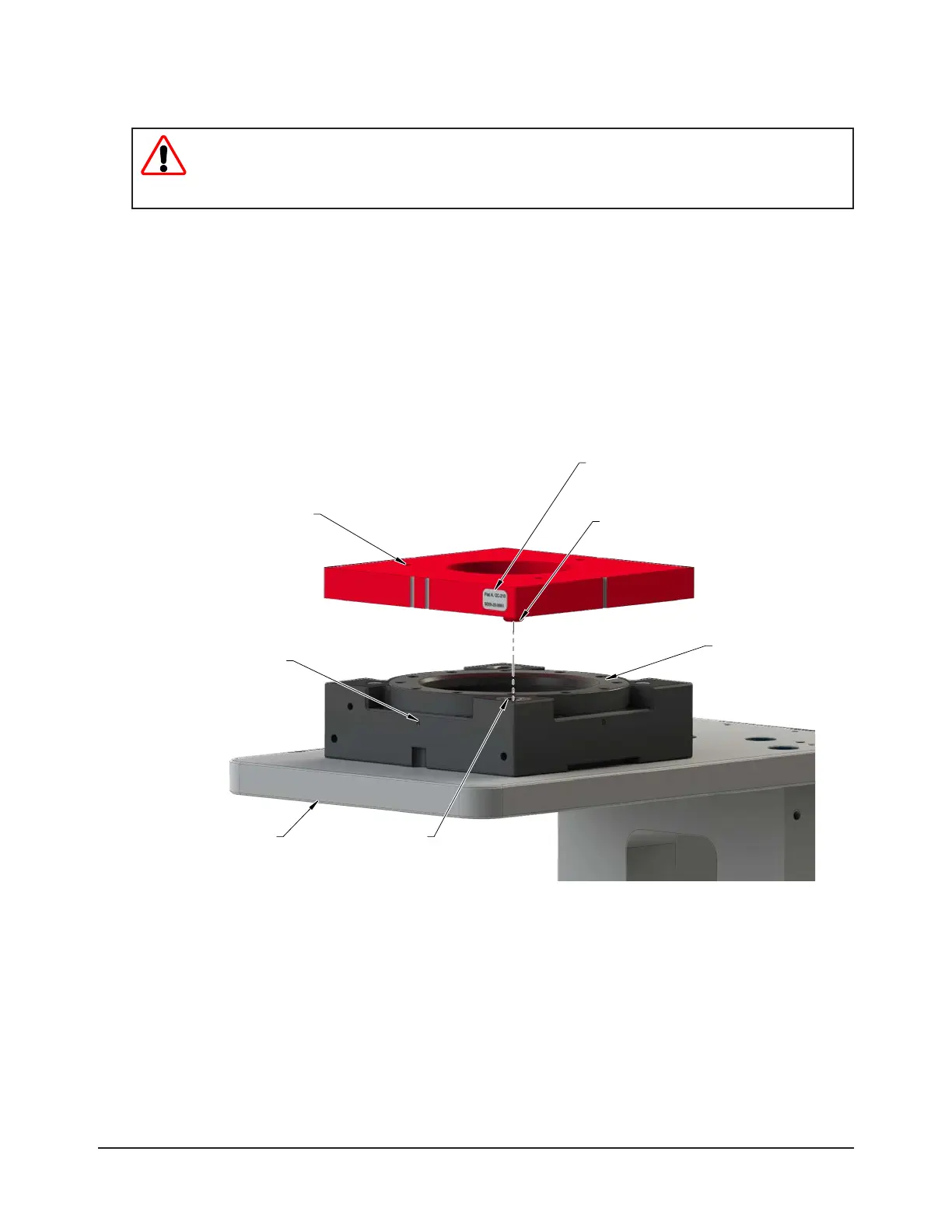
1. Place the Tool plate in the tool stand. Robot programs should be written with the Tool plate resting in the Tool
stand.
2. Orient the Tool Side Teaching Aid such that the ‘A’ at corresponds to the ‘A’ at on the Tool plate.
3. Mount the Tool Side Teaching Aid over the Tool plate by inserting the (2) locating bosses into the alignment
bushings. The magnets in the Teaching Aid attach to the Tool plate.
Figure 3.1—Tool Teaching Aid Installation (QC-210 Shown)
(2) Locating Boss
Flat A on the
Tool Plate
Bearing Race
Flat A (Label) on the
Tool Teaching Aid
(2) Alignment
Bushing
Tool
(3) Socket Head Cap Crew
that secures (3) magnet

 Loading...