Manual, Robotic Tool Changer Third Generation Teaching Aids
Document #9610-20-3370-02
Pinnacle Park • 1031 Goodworth Drive • Apex, NC 27539 USA • Tel: 919.772.0115 • Fax: 919.772.8259 • www.ati-ia.com • Email: info@ati-ia.com
10
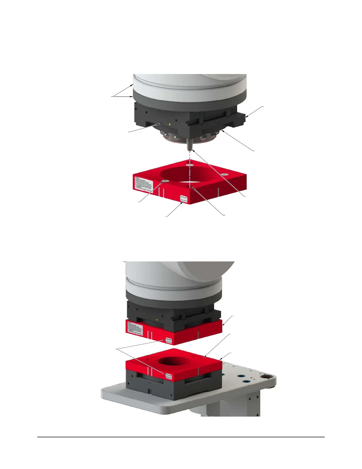
4. Align the Master plate at A to the Master Side Teaching Aid at A.
5. Mount the Master Side Teaching Aid to the Tool Changer Master plate by inserting the alignment pins into the
corresponding holes in the Teaching Aid. The magnets secure the Teaching Aid to the Master plate.
Figure 3.2—Master Side Teaching Aid Installation (QC-210 Shown)
(2) Alignment pin
(2) Hole for
alignment pin
in the Master plate
Flat A on the
Master Plate
Flat A (Label) on the
Master Teaching Aid
Robot and
Interfacing Plate
(For Reference Only)
Flange of the
Male Coupling
Master Plate
(4) Magnet
6. Position the Master plate directly over and parallel to the Tool plate. Align the Master and Tool ats; for
example: Master plate at A is aligned with Tool plate at A.
Figure 3.3—Positioning the Master Plate Towards the Tool Plate
Master Teach Aid
Tool Teach Aid
Tool Teaching Aid face must
be parallel with the
Master Teaching Aid face.
Flat IDs must match
(Flat A shown)

 Loading...