Manual, Robotic Tool Changer Third Generation Teaching Aids
Document #9610-20-3370-02
Pinnacle Park • 1031 Goodworth Drive • Apex, NC 27539 USA • Tel: 919.772.0115 • Fax: 919.772.8259 • www.ati-ia.com • Email: info@ati-ia.com
11
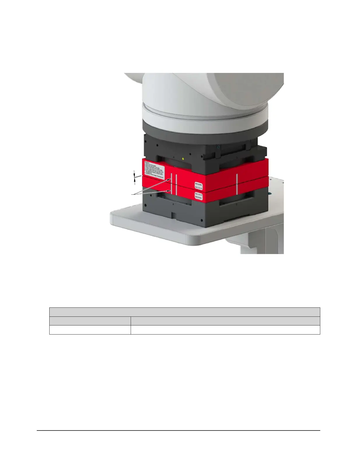
7. Move the Master plate slowly toward the Tool plate until the Master Side and Tool Side Teaching Aids are 1
mm apart.
8. Use the alignment marks or ats to align the Tool Side and Master Side Teaching Aids.
Figure 3.4—Final Alignment Position of the Teaching Aids
1 mm
Use marks to precisely
align the Master and Tool
9. Record the robot coordinates.
10. Move the Master plate away from the Tool plate so that the Master Side and Tool Side Teaching Aids can be
removed from the Tool Changer.
11. To account for the thickness of the Tool and Master Side Teaching Aids, the user must calculate a correction so
that the “pick-up” and “replacement” coordinates are correct. Perform the applicable calculation from Table 3.1
to determine the pick-up and replacement location.
Table 3.1—Calculating the Correct “Pick-Up” Coordinate
Teaching Aid Formula for “Pick-Up” Coordinate
(QC-210) 9120-210-TEACH3 ‘Z’ Pick-up Coordinate = (‘Z’ coordinate from Step 9)-(50 mm)

 Loading...