page 15/41
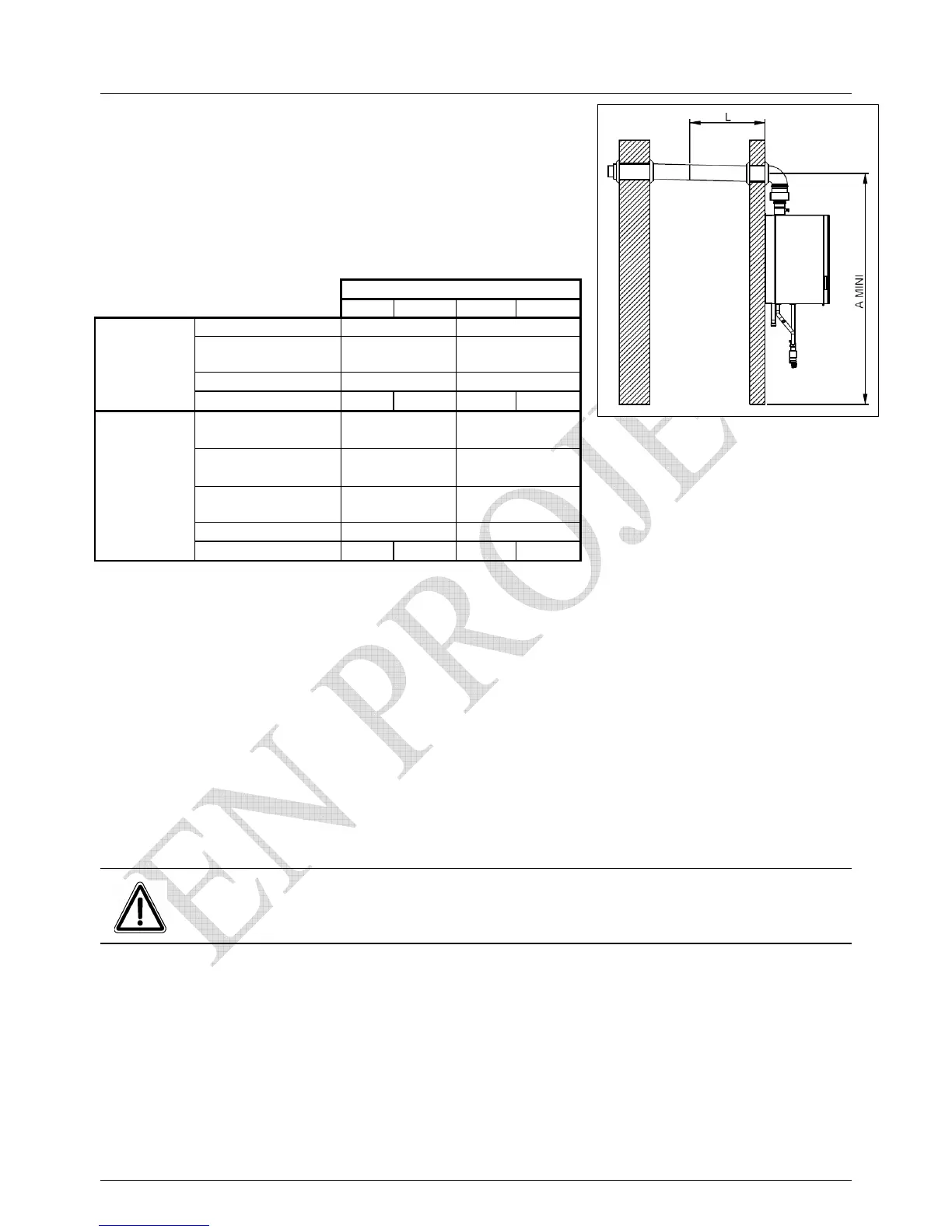
3.6 Balanced flue arrangement C13 and C33
The table below lists the components required for
this arrangement.
VF
60 100
Terminal C13
Code 059506 Code 059507
Ø of flue
Concentric
80/125
Concentric
100/150
A min (mm)
2125 2165
Horizontal
type C13
Lmax*
9 m 9** m
Terminal C33 noir
Code 059508 Code 059512
Terminal C33 ocre
Code 059509
-
Ø of flue
Concentric
80/125
Concentric
100/150
A mini (mm)
2035 2060
Vertical
type C33
Lmax*
9 m 9** m
* The dimension Lmax C13 + 90degC bend or C33
Calculations and recommendations carried out as on the previous page
For C13, make a 150mm hole in the wall for the 80/125 concentric flue
make a 180mm hole in the wall for the 100/155 concentric flue
** The V F 100 is set at Factory for balanced flues from 0-5 metres
for balanced flues between 5 metres and 9 metres, certain parameters
need adjustment as follows:-
 Loading...